


Adfustrnent
Procedure
-
4g4A/4g4Ap
Servtce
Vol.
1
o
I
o
a
o
o
o
t
o
a
I
t
O
O
o
o
a
t
o
a
a
o
a
O
a
o
o
o
O
o
a
o
t
o
o
o
I
o
o
o
o
o
o
o
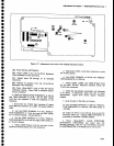
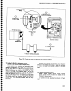
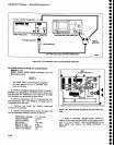
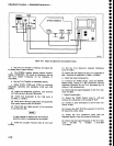
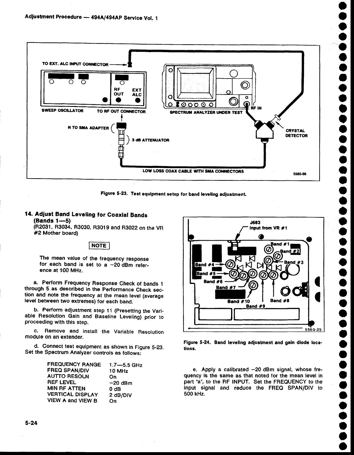
Figure
5-23.
Test
equipment
setup for
band
leveling
adiustmenl
1tt.
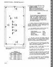
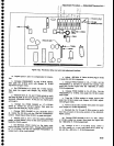
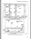
Adjust
Band Leveting
lor
Coaxial
Bands
(Bands
1-5)
(R2031,
R3034,
R3090,
R9019
and
R3022
on
the
VR
#2 Mother
board)
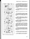
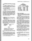
The
mean value
of
the
frequency
response
for each
band
is
set
to a
-20
dBm
refer-
ence at
100 MHz.
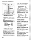
a.
Perform
Frequency
Response
Check of
bands 1
through
5
as
described
in
the
performance
Check sec-
tion and
note
th€
frequency
at
the
mean
level (average
level
between
two
extremes)
for
each
band.
b.
Perform
adiustment
step
11
(presetting
the
Vari-
able
Resolution
Gain and
Baseline
Leveling)
prior
to
proceeding
with
this
step.
c.
Remove
and
install
the
Variable
Resolution
module
on an
extender.
d. Connect test
equipment
as shown
in
Figure
5-23.
Set the
Spectrum Analyzer
controls
as
follows:
FREQUENCY
RANGE
1.7-5.5
GHz
FREQ
SPAN/D|V
10
MHz
AUTTO
RESOLN
on
REF
LEVEL
-20
dBm
MIN
RF ATTEN
O dB
VERT|CAL
DTSPLAY
2
dB/Drv
VIEW
A and
VIEW
B
on
5-24
Inpul trom VR
#1
I
I
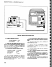
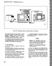
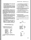
Figure 5-24.
Band leveling adiustment
and
gain
diode loca-
tion3.
e. Apply a calibrated
-20
dBm signal,
whose fre-
quency
is
the
same
as that noted for
the
mean
level in
part
'a",
to
the
RF
INPUT.
Set
the
FREQUENCY
to the
input signal and
reduc€ the FREQ SPANIDIV to
500 kHz.
TO
EXT.
ALC
IXP|JT@}|IGCTOR-
I
oo
I
o
r
o
RF
EXT
OUT
ALc
ot
o
o
sttEEP
osc|llATOR
TO
RF
OUT
@IOIECTON
I
SPECTRUT
AIIALY:ZER ITIOER TEST
LOW
LOSS
COAX
CABI."E WttH SflA
OO|,{€CTORS