


Performance
Check
Procedure
-
4g4Ll4g4Ap
Servlce Vot.
.l
PERFORMANCE
CHECK
PROCEDURE
1.
Check 10
MHz
Reference
Oscillator
Accuracy
(Aging
rate
<1
x
10-7)
The
10 MHz
Reference
Oscillator
accuracy
is not
a
performance
requirement;
however,
it
must
be checked
so
the
center frequency
accuracy
can
be verified.
Since
the
calibrator
is locked
to
the
10
MHz
oscillator
this
procedure
verifies
accuracy
by
counting
the
frequency
of the
calibrator signal.
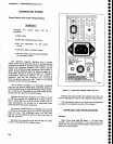
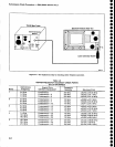
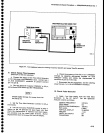
a.
Connect the
CAL
OUT signal
to
the frequency
counter. (Counters
with
a
frequency
range
above
200
MHz
may
require a
150
MHz
low
pass
filter
to €nsure
a
stable
trigger on
the
100
MHz
CAL
OUT
signat).
The Tektronix
DC
509
must.be
modified
to
accept
an
external
oscillator
reference.
Refer
to
the TMS00ffM5000
Series
Rear
Interface Data
Book,
part
No.
070-2099_04
for
modifi
cation
instructions.
b.
Connect the frequency
standard
to
th€ External
Frequency
Standard
Input
of
th€
frequency
counter.
c.
Check that
the
frequency
of
the
GAL
OUT signat
is 100
MHz
*10
Hz.
d.
Disconnect
the counter
from
the
CAL
OUT
con_
nector.
e. Reset
SPAN/DIV
to
500 kHz.
f.
Press
<Blue-SHIFT>
COUNT
RESOLN
and
enter
1 kHz for
a counter resolution
of
1 kHz.
g.
Press
COUNT and
note
that the
error
over
several counts
does not exceed 1 kHz.
h. Reset
the sPAN/Dlv to
200
kHz
and
repeat part
g.
i.
SEt
thE
CENTER FREOUENCY
tO
1.8
GHZ Or
1.7
GHz
and repeat
the
counter accuracy
check for
this
end of the
band.
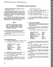
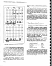
3. Check Counter
Sensitivity
(At
least
20
dB above
the
average
noise level
at
center screen
and no more
than
60 dB down from
the
refer€nce
level)
a.
Apply
the
CAL OUT
signal
to the
RF
INPUT via a
1
dB and a 10
dB
step attenuator.
Set
both
attenuators
for
0 dB
attenuation.
b.
Set the Spectrum
Analyzer
controls
as
follows:
o
o
o
o
o
o
o
o
o
o
a
o
o
a
o
o
o
o
o
o
o
o
o
o
o
o
o
o
o
o
o
o
o
o
a
O
O
o
o
o
o
o
o
o
CENTER FREOUENCY
sPAN/DrV
RESOLUTION
BANDWIDTH
REF
LEVEL
NARROW
VIDEO FILTER
VERTICAL
DISPLAY
TrME/DtV
TRIGGERING
100
MHz
1 MHz
1 MHz
0 dBm
On
10 dB/Drv
AUTO
FREE RUN
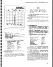
2.
Check
Counter
Accuracy
[CF
x
gslslsnce
Frequency
Error
+ (10
+ 2N)Hz
+
l LSD
a.
Set
the Spectrum
Analyzer
controls
as
follows:
b. Apply
the
CAL
OUT
signat
to
the RF
lNpUT, and
center
the 500
MHz
marker
calibrator
harmonic.
c. Press <Blue-SHtFT>
COUNT
RESOLN
and
enter 1
Hz via
the Data
Entry
keypad.
d. Press
COUNT
and
note
that
the error over
several
counts
does
not
exceed
.lSHz.
The factor
(CF
x
Reference Frequency
Error)
is
canceled
when
the
CAL OUT signal is
used.
4-6
c,
Set the
1
dB and 10 dB
attenuators
such that the
signal amplitude
is approximately 20
dB
above
the
noise floor.
d.
Press <Blue-SHIFT>
COUNT
RESOLN and
enter
1
Hz via
the
Data
Entry
keypad.
e.
Press
COUNT
and note
that the
counter
is
count-
ing
the
signal with
the
accuracy noted in
performance
check
step
2.
f. Reset
SPAN/DIV ancl RESOLUTION
BANDWIDTH
to
100
Hz,
REF LEVEL
to
-30
dBm,
and activate
WIDE
VIDEO
FILTER.
g,
Reset
the
1
dB
and 10 dB attenuators
such
that
the signal amplitude is approximatety 60 dB
down
from
the reference level.
h.
Press
COUNT
and
note
that
the
counter
is count-
ing
the
signal with
the
accuracy noted in
performance
check
step
2.
CENTER FREOUENCY
sPAN/DrV
AUTO RESOLN
REF
LEVEL
VERTICAL
DISPLAY
TrME/DrV
TRIGGERING
500
MHz
2AkHz
On
-30
dBm
10
dB/Dlv
AUTO
FREE
RUN