


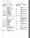
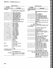
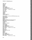
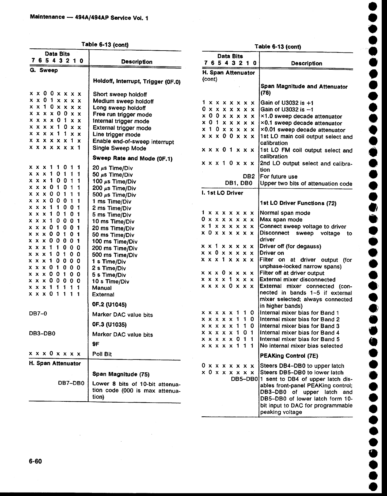
Table
6-13
{cont)
Malntenance
-
494A/4g4Ap
Servlce
Vol.
1
Data
Bits
76549210
Descriptlon
G. Sweep
I
o
o
o
I
o
)
t
o
o
a
o
o
o
o
I
o
I
o
3
a
o
o
o
C
o
o
o
o
a
o
o
o
o
o
o
o
a
a
O
o
o
t
o
xx00xxxx
xx0lxxxx
xxl0xxxx
xxxx00xx
xxxx0lxx
xxxxl0xx
xxxxllxx
xxxxxxlx
xxxxxxxl
0
0
0
0
0
0
1
1
xxx1101
xxx1O11
xxx1001
xxx0101
xxx0011
xxx0001
xxx1100
xxx1010
xxx1000
xxx0100
xxx0O10
xxx0000
xxx1100
xxx1010
xxx1000
xxx0100
xxx0010
xxx0000
xxx1111
xxx0111
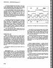
Holdoff,
Interrupt,
Trigger
(0F.0)
Short sweep
holdoff
Medium
sweep
holdofi
Long
sweep
holdoff
Free
run
trigger
mode
Internal
trigger
mode
Extemaltrigg€r
mode
Line
trigger
mod€
Enable
end-of-sweep
interrupt
Single
Sweep
Mode
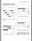
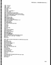
Sweep
Rato
and
Mode (0F.1)
20
ps
Time/Div
50
ps
Time/Div
100
ps
Time/Div
200
ps
Time/Div
500
ps
Time/Div
1 rns
Time/Div
2
ms Time/Div
5 ms
Time/Div
10
ms
Time/Div
20
ms
Time/Div
50
ms
Time/Div
100
ms
Time/Div
200
ms Time/Div
500
ms
Time/Div
1
s Time/Div
2 s
Time/Div
5 s
Time/Div
10
s Time/Div
Manual
External
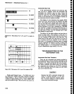
0F.2 (U104s)
Marker
DAC
value
bits
0F.3
(U103s)
Marker
DAC
value
bits
9F
PollBit
DB7-O
DB3-DBO
xxx0xxxx
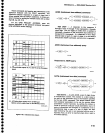
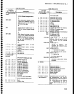
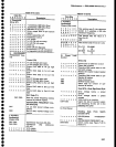
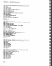
H.
Span
Attenuator
DB7-DBO
Data
Bits
76543210
H.
Span
Attenuator
(cont)
lxxxxxxx
0xxxxxxx
xO0xxxxx
x0lxxxxx
xl0xxxxx
xxx00xxx
xxx0lxxx
xxxl0xxx
DB2
DBl,
DBO
l. 1st
LO
Driver
0xxxxxxx
x0xxxxxx
DBs-DBO
Descrlption
Span Magnitude
and
Attenuator
(76)
of
U3032
is
+1
Gain
of
U3032 is
-1
x1,0
sweep
decade attenuator
x0.1
sweep
decade attenuator
x0.01
swe€p
decade attenuator
l st LO
main
coil output
select
and
calibration
1st
LO FM coil
output
select
and
calibration
2nd
LO output
select
and
calibra-
tion
For
future
use
Upper
two
bits
of attenuation
code
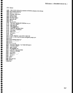
lst
LO Driver Functions (72)
Normal
span
mode
span
mode
sweep
voltage
to driver
Disconnect
sweep
voltage
to
driver
Driver
off
{for
degauss)
Driver
on
Filter on
at
driver output (for
unphase'locked
narrow
spans)
Filter off
at
driver output
External
mixer
disconnected
External
mixer connected (con-
nected in
bands 1-5
if external
mixer selected; always
connected
in higher
bands)
Internal
mixer
bias
for Band
1
Internal
mixer
bias
for Band
2
Internal mixer
bias
for
Band 3
Internal mixer
bias
for Band
4
lnternal
mixer
bias
for
Band 5
No inlernal
mixer bias selected
PEAKing
Control(7E)
Steers DB4-DB0
to upper latch
Steers
DBs-DBo
to
lower
latch
1 sent
to DB4 of upper
latch dis-
ables
front-panel PEAKing
control;
DB3-DB0
of upper latch
and
DBS-DBO
of lower
latch form 10-
bit
input
to
DAC
for
programmable
peaking
voltage
lxxxxxxx
0xxxxxxx
xlxxxxxx
x0xxxxxx
xxlxxxxx
xx0xxxxx
xxxlxxxx
xxx0xxxx
xxxxlxxx
xxxx0xxx
10
10
10
01
11
11
xxxxx
xxxxx
xxxxx
xxxxx
xxxxx0
xxxxxl
Span
Magnitude (75)
Lower
8
bits of 10-bit
attenua-
tion
code
(000
is max
attenua-
tion)
Table
6-13
(cont)
6-60