


o
a
o
a
o
a
t
I
o
o
I
t
o
o
a
I
)
o
a
o
t
a
o
a
o
C
t
o
t
o
t
o
o
a
a
a
t
o
o
o
o
o
o
o
lithium
battery
8T2040,
or
in
option
3g,
silver
batteries
(Eveready
392
or
equivalent).
See
the
Maintenance
section
for
replacement
information.
Each
ol
the
non-volatile
memory
lcs
require
less
than
2
rl.
They
wiil
hold.
data
as tong
as
the
battery
voltage
is
above
2.SV.
In
the
batte{
circuit,
RIO3O
and
R2037
protect
the
battery
against;ccidental
short
circuits.
The
jumper
on
pins
i
anO
e
of
p1040
provides
an
easy
way
to
rernove
power,
thus
clearing
ali
data
in
the RAM.
The
microprocessor
uses
ftip-flop
U4O3O
to
power-
up
and
enabte
the
battery-backed-up
RAMs.
tnitiatty,
U4.030.is
reset
by
the
RESET
tine
goiog
tow.
This
dis_
ables
the
non-volatit€
RAMs,
U1020
and-U1030.
As
part
of
the
_initialization
sequence,
the
microprocessor
writes
to instrument
bus
address
73
to set
U40gO,s
output
high.
(U4040
decodes
bus
address
73).
This
ailows
q?qq to^c-harge
to +5
V. turning
on
e20i5.
e2035,
and
Q2CX!7.
Q2037
connects
the
+5
V
suppty
to th€
RAMS,
power-supply
inputs,
back-biasing
CRf03O
and
discon-
llcling
the
battery.
e202S
turns
on
e2OgO,
puuing
the
CE
inputs
low,
allowing
the
micropro"e"soi
to
use
the
RAMs.
Theory
of
Operation
-
4g4Al4g4Ap
Service,
Vol.
1
On
power-down
the
microprocessor
sets
the
output
of
U4030 low.
After
C2090
discharges,
e2O2S,
O20bO,
02035, and
Q2037 switch
off.
R2Og2
puils
the
CE1
lines
high,
to
the RAM
suppty
vottage,
disabting
the
memory.
As
the
suppty
vottags
fails,
CR2030
swiiches
9{, -and_
the
battery
begins
supptying
power
to
the
RAMs.
R2036
and
R3034
insure
that
the-CE2
tines
are
grounded,
not
floating,
in
the
standby
condition,
as
is
required
for
lowest
current
drain.
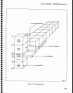
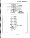
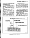
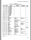
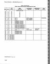
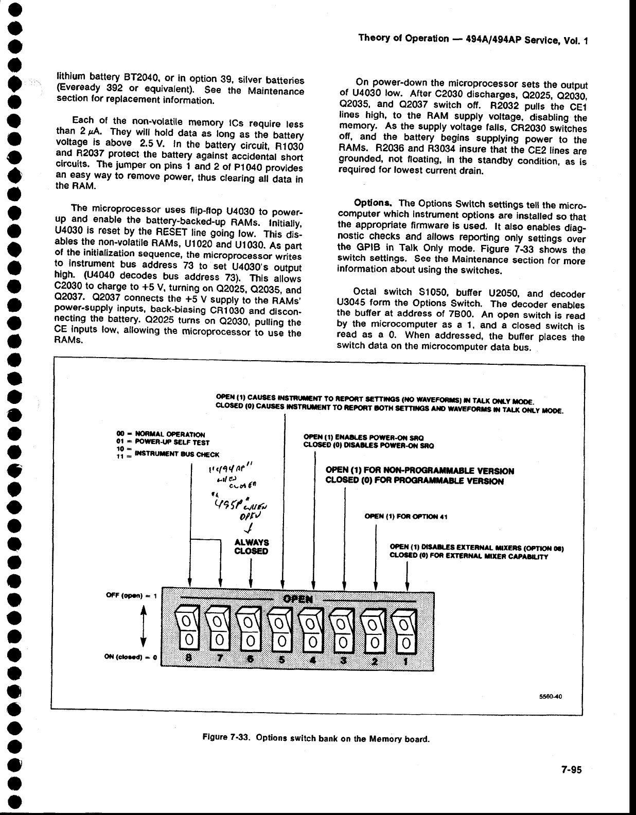
Options.
The
Options
Switch settings
tell the
micro-
cornputer
which
Instrument
options
are
instaled
so
that
the
appropriate
firmware
is
used.
lt also
enables
diag-
nostic
checks
and allows
reporting
only
settings
ovir
the
GPIB in
Tatk
Only
mode.
Figure
7€B
shows
the
switch
settings.
See the
Maintenance
section
for
more
information
about
using
the switches.
Octat switch
S1050,
bufer
U2050,
and
decoder
U3045
form
the
Options
Switch.
The
decoder
enables
the
buffer
at
address
of
7800.
An open
switch
is read
by
the microcomputer
as
a 1,
and
a
closed
switch
is
read
as a
0. When
addressed,
the
buffer
places
the
switch
data
on
the microcomputer
data
bus.
OFEX (1'
CAUS€S
OISTRLn|CTT
TO IEPORT
sG'T|r{CS
(XC'
WAVEFOiT'
il
TALX
OitV
rcOG.
cLos€o
{ol
cAUs€S
fisrRrtrErr
ro
iEFroRr
tor}r
sdrrnrcs ero
wevrroers
n-iirr.x
oi{_y
roo€.
O
-
r|(tiIAL
OPERATTX{
ot
-
ProwER.ttP
s€LF
tEst
ff
:
n sr"rrcrr
qrs
crccr
O?EX
(1)
EXAa
€3 P'OUER-OIa
SAO
c|'os€O
(Ol
OtsAlrEs
FowEi-or
sno
1t
<114 A?tt
"{
'lunr
6o
oPEN
(1'
FOR ilOil-pROcRAfltAErE
yERs|OX
CLOSED
(Ol
FOn PnOORAm|ABTE
yERsptil
oPEX
(r)
FOR
OFTtOil
al
oPEn
(1)
O|S
ILCS
€ITERilAL
nXEiS
(Opnofl
6t
c|.oSco
(0,
FoR
ETTGRilaL
nxER
cap
auw
OFF
(oporl :
l
t
I
Oil
(cb..dt -
O
Flgure
7.33.
Options
switch
bank on
tha Memory
board.
7-95