Maintenance
-
494A/494Ap
Service
Vot.
1
!. A"
microcomput€r
next
tests
U2015, a
timer chip
on
th€
Procassor
board.
lf any
of
the
timers
in
U201b
result
in
timo
d€lays
that ar€
too
short
or
too long,
the
test stops
with LED
DS10Sg
on
th€
GptB
board tit.
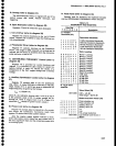
6. The microcomputer
resets
the
GplA,
U2050,
on
the
GPIB board and
checks
to see
that
the
GptA
is not
addressed
to
talk or
listen.
The
GplA is
set
to
the
listen-only
mode
and
checked
to
see
that
it is
addressed
to listen.
The
GplA
is
then set
to the
talk_
only
mode
and
checked
to
sEe
that
it
is
addressed
to
talk. lf any
part
of
this step
falls,
the
test stops
and
LED
DSl052 on
the
GPIB
board is
ilt.
lf all steps
in
the
test arE
successfully
completEd,
the microcomputer
lights
LED
DS10S4 on
the
GptB
board.
The
LED is
lit
continuously
if
no
empty
ROM
sockets
are
found,
or
putsed
the number
of
times
corresponding
to the
number
of
empty
RoM sockets
found.
lf
the number
of
pulses
is
greater
than
the
number
of
absent
ROMs,
a
ROM
(or
ROMs)
was
missed
in
step
4. Look
tor
a
problem
on
the chip-s€lect
line
or on
the D7
data
bus line.
lf
th€ microcomput€r
system
passes
the
t€st,
but
does not control
the instrum€flt,
run the lnstrument
Bus
Check
describ€d
tater
in
this section.
Address
Bus
Test
Select the address
bus
t€st
by moving
jumper
P3015 on the
Processor
board
to
th€ TEST
position.
This
forces
the
microprocessor
(U1025)
data
linss
to
hexadecimal
5F. As
a
result,
the
microproc€ssor
con-
tinuously
executes
a
CLR B
instruction,
and rep€titively
cycles
through
all
of itE
address
space.
There
should
bi
a
known
pattern
on
the
microcomputer
address
and
control
lines and
at
th€
output
of
th€ address
decoders.
This
allows
qualified
servic
personnel
to corr€ct
prob-
l€ms
that
pr€vont
the
microcomputer
from
running
its
self-t€st.
The
spectrum
analyzer
will
not
function
while
run-
ning
this
test.
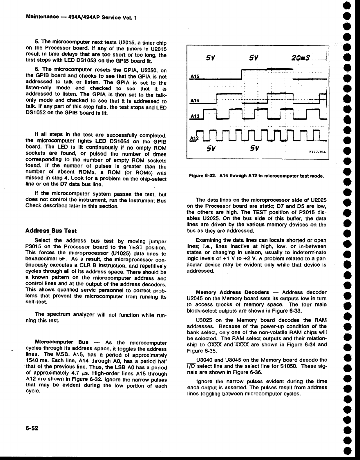
Mlerocomputer
Bus
As
the
microcomputer
cycles
through
its
address
spac€,
it
toggles
the
address
lines.
The MSB,
A15,
has
a
period
of
approximately
1540
ms. Each
line,
414
through
A0, has
a
period
haif
that
of
the
previous
line.
Thus,
the
LSB
A0
has
a
period
of
approximately
4.7
ps.
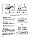
High-order
lines
A15 through
A12
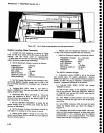
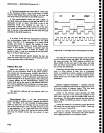
ara shown in
Figure
6€2.
lgnore
the narrow
pulses
that
may be
evident
during
the
low
portion
of each
cycle.
Figure
6-32. A15 through
A12
ln
mlcrocomputor
test
node.
The
data lines
on
the microprocessor
side of U2025
on
the
Processor board are static;
D7 and
D5 are
low,
the
oth€rs
are high. The
TEST
position
of
P3015 dis-
ables
U2025. On the bus
eidE
of
this buffer,
the
data
lines are
driven by
the
various memory
devices
on
the
bus
as
they
are
addressed.
Examlnlng the data lines can locate
shorted or
open
lines; i.e.,
lines
inactive
at hlgh, low, or
in-between
states or
changing
in
unison,
usually to
indeterminate
logic lev€ts of +1 V
to
+2
V. A
problem
r€lated
to
a
par-
ticular
device may be
evident
only while
that device
is
addressed.
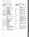
Memory Address Decoders
-
Address decoder
U2045 on
the Memory
board sets its outputs low in
turn
to
access
blocks
of
memory
space.
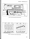
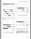
The four
main
block-select orrtputs
are shown in
Figure
6-33.
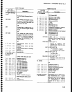
U3025
on
the
Memory
board decodes
the
RAM
addresses. Because of
the
power-up
conditlon of
the
bank
select, only one of
the non-volatile RAM
chips will
be
selected.
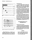
The RAM seleot outputs
and
their relation-
ship
to 6-ffi andl{ffi are
shown in
Figure 6€4
and
Figure
6-35.
U3040
and
U3045
on
the
Memory
board decode
the
T/O-
select
line and th€
select line for
S1050.
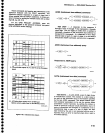
These
sig-
nals
are shown
in Figure
6€6.
lgnore
the
narrow
pulses
evident
during
the
time
each
output is asserted.
The
pulses
result from
address
lines
toggling between
microcomputer
cycles.
a
o
o
t
I
o
o
I
o
I
I
I
o
o
o
o
o
o
o
o
a
o
I
o
o
I
a
o
o
I
o
a
c
o
o
o
O
e
o
o
o
o
o
o
6-52


