o
o
a
o
a
o
o
o
o
O
o
o
o
a
a
o
a
o
I
o
o
o
o
t
o
o
a
o
O
I
o
a
O
o
o
o
o
o
o
o
o
o
o
o
Marker
DAC
The
Marker
DAC
circuit provides
a
dc
level
corresponding
to
the
marker
sweep
position.
This
occurs
during
retrace.
allowing
osciliators
to operate
long
enough
for
the
counter
to
get
an
accurate
reading
gJ
the
marker position.
The
processor
loads
twelve
bits
to Marker
DAC
UlO47.
Thls
dc
level
reptaces
the
swe€p
ramp
during
th€
during
the
retrace
time
when
the
swe€p
is inactive.
The
Marker
circuits
on
the
Horizontal
Digital
Storage
board
reads
the
dc voltage
and
recon-
verts
to
digital
to feed
the
processor.
ihe processor
compares
these
bits
to
the
location
of
the marker
in
digitar
storage
and
adjusts
the
Marker
DAC
bits untir
the
digitized
voltage
matches
the
marker position.
U1047
is
a
12-bit
DAC.
The
12
bits come
frorn
registers
Ul040
and
Ul045,
the address
0F
second
and
third
extended
address
registers.
The
DAC
produces
a
current
output,
which
U2040
converts
to
a voltage.
U2045
sums
an
offset
voltage, giving
a
voltage
range
of
about
*9
volts.
This
voltage
range
is greater
than
the
range
of
the sweep
ramp.
This
fact,
and
the DAC
hav-
ing
twelve
bits
guarantee
that
there
will
be a
twetve
bit
number
for
the DAC
for
each
of
the 1000
digital
storage
points.
Sweep
Control
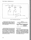
U1025A
is
the
Sweep
State
Control
flip-flop.
When
reseti
the
high
at
the
Q(bar)
output
turns
off
FET
01062
and
allows
-the
integrator
capacitors
to
charge.
When
the
sweep
state
control
ftip_flop
is
set,
by a
iow
on
pin
4,
its
Q(bar)
goes
low.
This
switches
the
output
of
corn_
parator
U10608
so
its
output
turns
e1062
on
and
9j:!!lln""
the
timing
capacitors.
The
e(bar)
output
of
U1025A connects
to
pin
5
of
Ut017A
so
this low
switches
the
output pin
6 to its
high
impedance
state
(its
output
is open
coltector).
The
Q outpui
of
U1025A
is
high.
Both
U10t6A
and
U,t0168
wheie previousty
set
when
the
Q
output
was
low.
This
staris
lhe holdoff
cycle
or
retrace
time
which
is
described
in
detail
further
on.
The
Sweep
State
Controt-flip.flop
Ul025A,
is
set
by
a
low
out of
NOR
gate
U2O20A
when
either
the
EOS
{end-of-sweep)
or
the
ABORT
SWEEP
tines
go
high.
ABORT
SWEEP
is
gen€rated
when
a
1
is
written
to b0
at
address
1F.
The
Sweep
Control
flip-flop
is reset
by
either
a
trigger
signal
from
multiplexer
V2026
or
a
hioh
on
the MNL
or
EXT
SWp
line.
The
microcorputlr
writes
to
bits D2
and
D3
at
subaddress
1 of
address
0F
for
the manual
or
external
sweep
mode.
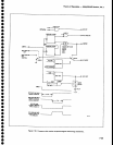
Theory
of
Operation
-
4g4Al4g4Ap
Service,
Vot.
.l
Trigger
Control
A
sweep
is
initiated
by the microcomputer,
in single
sweep
or
manual
mode
as
noted
abov€,
or
by one
of
three
trigg€r signats
selected
by
the multiplexei
U2020.
Oata
bits
D2
and
D3 at addrEss
0F.0
select
the
input
trigger
signals
and
rout€
tham
to the
clock
input
of
U10168.
During
swe6p
time
thg flipf,op
U10168
is
set
by a
low on
th€
Q
output
of
U1025A.
The
high
on
the
Q(bar) output
of
u1025A
is
atso
applied
through
an
inverter
buffer in
U1O17A.
The
resultant
low
out
discharges
holdoff
capacitor
C3032
at
the
input
to u30258.
The
output
of
u30258
is
tow
so
the output
of
NAND
gate
u1020D
is
high.
Ftip-flop
U10168
requires
a
high-to-low
transition
to ctock
any
input
through.
Since
lt is
high, incoming
trigg€r
signati
will
have
no efiect
on
the circuit.
At
the
end
of
sweep,
the
e(bar) output
of
U1025A
goes
low.
This
s\witches
the output
of
U1017A
to
its
high
impedance
state and
tha
holdoff
capacitor,
CgOg2,
starts
to charge
towards
+15
volts
through
RgO30.
When
it reaches
+5
volts
the comparator
output
switches
high.
This,
along
with
a
high
on
pin
13
of
NAND
gate
U1020D,
causes
the
output
to
go
low
and
the
high-to-low
transition
clocks
U2026 so
the incoming
lrigger
signal
can
now clock
U10168
and
produce
;
high
at
the
Q(bar)
output.
This
is
gated
through
UZO26
to the input
ot
u2020c,
so
the output
of
the NoR
gate
will
now
reset
the Sweep
State
Control
flip-flop,
U1025A,
and start
a
new sweep.
In
the free-run
mode
the multiplexer
U2026, selects
the
+5 volts
on
pin
5.
This
high is
clocked
through
to
the
sweep
state
control flip-flop
immediatety
after
retrace.
fncoming
trigger signals
are ignored
and
the
sweep
runs
automatically.
In single
sweep
mode
the sweep circuit
cannot
be
re-triggered
until
it is
armed
by the
microcomputer.
Bit
D0
is set
high
at
subaddress
0
of
address
0F
(U1095-6).
This
appears
as
a
high on
pin
2 of
U4010A.
Since
U1016A
has
been
set
by the
previous
sweepr
the two
highs
at
the input
produce
a low
at
pin
13 of
Ul020D.
Therefore,
incoming
triggers are
disabted. The sweep
is
now
in an
idle
state and
cannot
run until
the microcom-
puter
arms
the
trigger
circuit
again.
This is
done
by
set_
ting
bit D3 high
at address
lF,
which
produces
a high
out
of
U1026
pin
3
and
clocks
flip-flop
Ut0t6A. The
resultant
low
at
pin
1
of
u4010A forces
a
high at
pin
11
of
U1020D, and
arms
the trigger
circuit. Thus
a signal
can
now trigger
the sweep circuit
and
the
singte
sweep
cycle
repeats.
7-63


