


o
o
o
o
o
o
o
o
o
o
o
o
?
o
o
o
a
o
o
o
o
o
o
o
o
o
o
o
o
o
o
o
O
o
O
o
a
o
o
o
o
o
o
o
CR4078
and
CR40Z
at
the input
to
U4ogil, protect
the input
against
excessive
voltage
excursions.
The
high-voftage
osciilator
is
protected
-Oy
enfteft
RgOTg,
(d
?/
and
R4074
in
case
the +i00
V suppi
should
fait.
Nor_
mally,
CR1037
is
back
biased.
ti
tne
+t00V
is
not
present,
CR1037
conducts
and
clamps
the
input
nega_
tive;
the output
of
U4093
swings
negative
ancl
e1073
remains
cut
off.
This
circuit
ensurei
that
e1073
witl
be.gin
to
oscillate
only
after
the
100
V
supply
r€aches
a
voltage
sufficient
to sustain
oscillation.
ChiOzZ (in
the
regulator
output
circuit)
protects
the
base
ot
OtOZg
from
excessive
negative
voltage.
Z-Axis
Clipper
This circuit
consists
of
diodes
CR1056
and
CR1046,
plus^associated
components.
The
22iyac
trom
pin
i
of
T2065
is coupted
through
C1O5g
and
R104g
to
the
junction
of
GR1046
and
CR.I0S6.
The
regutator
circuit,
that consists
of
VR1041,
R2050,
R2O4d,
and
e204g
holds
the cathode
of
CR1046
at
approximatety
*100
V
to
143,V,
depending
on
the setting
of
R2040.
CR1O46
and
CR1056
ctip
the
incoming
2llyac.
R2040
is
adjusted
to completely
cut-off
the crt
with
Z-Axis
DRIVE
at
minimum.
The
voltage
that
passes
the clipper
circuit
is
coupled
through
Cl091
to
the
Z-Axis
rectifier.
_
The
clipped
Z-AX|S
DRTVE
signal
is
rectified
by
CR2044
and
CR2046,
which
are
1ne
principte
com-
ponents
of
the
second
section
of
the Z-Axis
circuit.
The
rectified
voltage
is
then
fed
to
the
grid
of
th€
crt.
Cl041 couples
the fast
changes
of
drive-voltage
to
the
gl
griO
to
.speed
up
the response
of
the
grid
circuit.
Th€
crt
^gri^d ^is
protected
from
high_voltage
arcs
by
neons
DS20S2,
DS2054,
anO
D$2057.
RlO43
protect;
CR2046
and
CR2044,_
respectively,
from
high-vottage
surges
if
the crt
should
arc.
cRT
READOUT
(D|AGRAM
30)
The
Crt Readout
assembly
stores
readout
charac-
ters and
generates
deflection
and
Z-Axis
signals
to
display
those
characters.
tt also
handles
the
frequency
dot marker
display.
Both
characters
and
frequency
dot
displays
are
time-shared
with
the spectrum
trace.
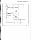
Generating
Readout
Crt readout
is
handled
by
sequential
logic,
clocked
at
3.41 MHz,
supptied
by
the
piocessor
Loard.
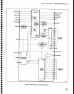
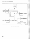
The
readout
circuitry
(Figur€
7-17)
is composed
of
the fol_
lowing
€lements.
1. Readout
On Timing
_
RAM
for
character
storage.
Theory
of
Operation
-
494A/4g4Ap
Servlce,
Vol.
1
2.
Character
Count€r
-
to acc€ss
the
RAM
and
control
the scan.
3.
Character
Generator
-
to
unblank
the crt
b€am.
4, DIA
Converters
-
to
deflect
the crt
beam.
5. Instrument
Bus
Interface
-
to
store
characters
and
control
the
display.
A
more
detailed
block
drawing is
provided
adjacent
to Diagram
30.
Forty characters
can
be displayed
per
line,
with
up
to sixteen
lines
selected.
Normally,
up
to
three
lines
are
displayed
while simultan€ousty
displaying
the
spec-
trum.
When
over
three lines
are
to
be
displayed,
the
spectrum
display is
disabled
to
keep
the readout
refresh
rate
above
60 Hz.
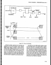
Readout-On/Olf
Timlng.
Characters
are
written
one
at
a
time.
This allows
a
portion
of
the
spectrum
to b€
drawn
between each
character.
Th€
character
duty
cycle
is
between
10%
and 257"
because
it
varies
with
the character
drawn.
The
time
sharing
between
charac-
ter writing
and
spectrum
display
is
pseudorandom
to
reduce
the effect
of
gaps
in
the spectrum
display
by
moving
them on
the trace.
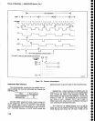
The readout-off
time is set
to 140
ps
by one-shot
multivibrator
Ul055
(Figure
7-18).
Ftip-flop
UtO41B
asserts
GEN RUNNING
after
ul055
tim€s
out, altowing
a
character
to
be drawn.
After a
character
is
written.
ROW
0
COL 0
resets
the flip-flop,
which
clocks
off
time
one-shot
U1055.
The
ON control
bit
must
have
been
asserted
by the microcomput€r
to
get
readout
(as
described
under Instrument
Bus
Interface
later
in
this
section).
lf
BLANK
(MSB
of
the
character
data)
is
not set,
the
GEN RUNNTNG
flip-flop
unasserts
R/o
oFF
through
oR
gate
U20448;
this switches
the
readout
deflection
sig-
nals
for
the deflection amplifier
inputs (Diagram
271.
BLANK
can
be set
by the microcomputer
to load a
space
into
the
character
RAM so
the readout
does not
use
time
for
the
spectrum
trace
to scan
a
blank charac-
ter.
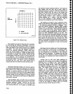
Character Scan.
Although
the 8678
character
g€n-
erator
lC,
U2048,
is
often
used
in
raster
scans,
in
this
application
it is used
to write complete
characters, as
shown
in Figure
7-1
9.
A character
is
drawn
as
a
pat-
tern
of
dots
in an
8 x
I
matrix
wherE
the top
row and
first
three
columns
are
blank. These
blank dots
allow
for
beam
retrace
and
spacing.
The
idle
position
between characters
is indicated
on
the
figure.
7-51