


o
o
o
o
o
o
o
I
o
o
o
o
o
I
I
I
I
o
a
o
t
a
o
o
o
o
o
a
o
I
I
o
I
o
o
O
o
I
a
o
o
a
o
o
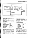
_ ^
wIT
the
foop
is
unlocked,
RF
teakage
from
the
16-20
MHz
osciilator
buffer
is
present
.ip224
with
a
level
of
--35
dBm.
The-amplified
Omeience
frequency
can
be
monitored
at
Tp20gS.
Another
check
of
phase
lock
operation
can
be
done
by
measuring
the
dc
voltage
on
the
21g2
MHz
Tune
Line
at.feedthrough
capaciior
C22Og.-ttominally
itris
voltage
is approximately
-5
V
when phase
lock€d.
Use
a
FREQ
SPAN/D|V
of
S00
kHz
or
greater
before
measuring.
lf
there
is
no
difference
freq-uency,
the
vol-
tage
wilt
be about
0 V.-
l
vottage
of
_13
V
may
indicate
loss
of
signal
from
the
VCO.
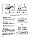
Narrow-band
noise
on
the
2nd
LO
signal
may
be
due
to
noise
modulation
of
ths
16_20
MiivCO.
trton_
itor
the
stgnat
at
the tg
MHz port
to
"""
ii
ttre
oscittator
signal
is
noisy.
Noise
on
this
line
is
often
caused
by
noise
on
the *12V
lines.
Use a
differentiat
oscillo_
scope
with
1
Hz
to
300
Hz
bandwidth
limits
to
check
supply
noise.
Measure
the
ac
Oifferentiat
Letween
the
supply
and
the
2nd
LO
housing.
Less
than
5
pV
peak-
to-peak
of
noise
will
cause
noticeable performance
jeOradatign.
Output
noise
from
the
shapel
is
typicaily
less
than
5
pV
peak-to-peak.
Maintenance
_
4g4N4g4Ap
service
vot.
I
.
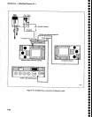
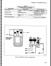
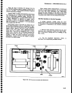
When
making
power
m€asurem€nts
of
microwave
circuitry,
at
circuit
board
interfaces,
use a coaxial
probe
with
v9ry
litfle
stray.
inductance
(see
figure'O-ee1
Ground
the outer
conductor
of
the
pioUe
tolhe
circuit
housing
as close
as
possible
to
the measurement
port.
Disconnect
other
loads
from
ths meaEurement
point.
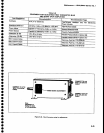
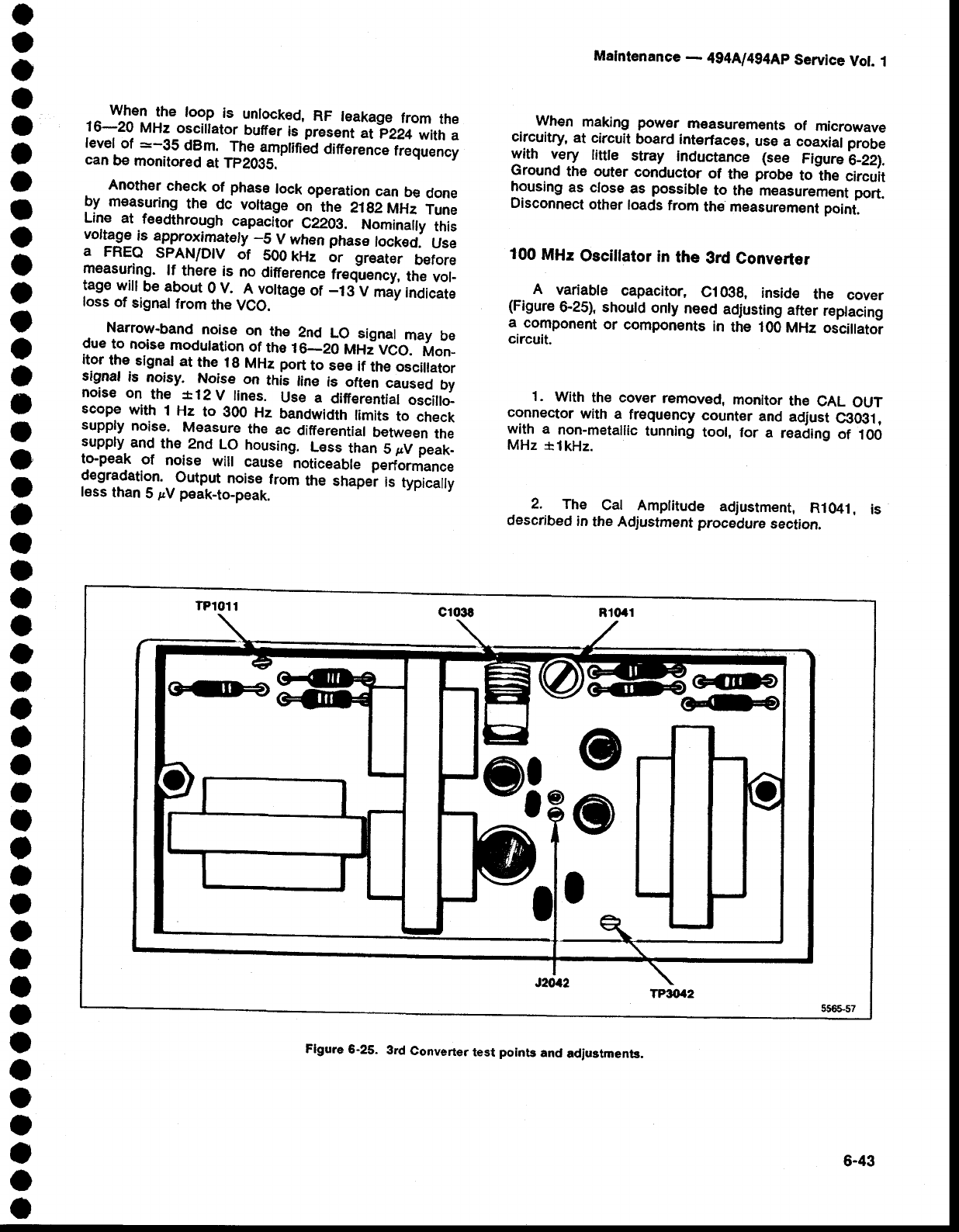
100
MHz
Oscillator
in
the
3rd Converter
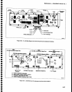
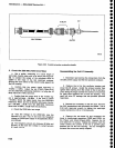
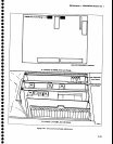
A
variable
capacitor,
C10gg,
inside
the
cover
(Figure
6-25), should
only
need
actjusting
after
reptacing
a.
component
or
components
in
the 100
MHz
oscillatoi
circuit.
1.
Wth
the
cover
removed,
monitor
the
CAL
OUT
connector
with
a
frequency
counter
and
adiust
Cgoiil
,
with
a
non-metallic
tunning
tool, for
a
reading
of
100
MHz
rlkHz.
2.
The
Cat
Amplitude
adjustment,
Rl041,
is
described
in
the
Adjustment procedure
section.
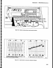
1?8
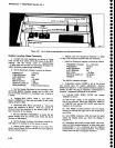
TPttt4!
Flgure
6-25-
3rd
Converter
test
poinb
and
adjustments.
6-43