


Theory of
Operatlon
-
4g4A/494Ap
Service, Vot.
1
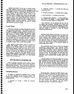
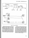
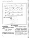
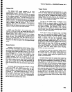
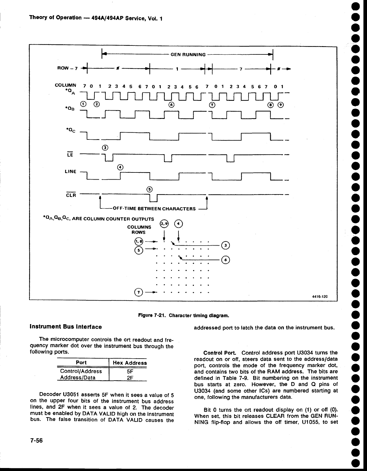
Flgure
7-21.
Character
timing dlagram.
o
o
o
o
o
o
o
o
o
o
o
o
o
o
O
o
o
o
o
o
o
o
o
o
o
o
o
o
o
o
o
o
O
o
o
o
o
o
o
o
o
o
o
o
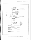
lnstrument
Bus
Interface
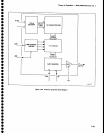
The
microcomputer
controls
the crt
readout
and
fre-
quency
marker
dot
over
the
instrument
bus through
the
following
ports.
Decoder
U3051
asserts
5F when it sees
a value
of
5
on
the upper
four
bits of
the instrument
bus address
lines, and
2F when
it
sees
a value
of
2. The
decoder
must
be
enabled
by DATA
VALID high
on
the
instrument
bus. The false
transition
of
DATA VALID
causes
the
7-56
addressed
port
to
latch the data
on
the
instrument
bus.
Conlrol
Port
Control
address
port
U3034 turns the
readout on
or
off, steers
data
sent
to the
address/data
port,
controls
the
mode
of
the
frequency marker
dot,
and contains
two bits
of the
RAM
address.
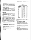
The bits
are
defined
in Table 7-9. Bit
numbering
on
the
instrument
bus
starts al zero. However, the
D and
Q
pins
of
U3034
(and
some other
lCs)
are
numbered
starting at
one,
following th€ manufacturers
data.
Bit 0 turns the crt readout
display on
(1)
or off
(0).
When
set, this
bit
releases CLEAR
from
the GEN
RUN-
NING flip-flop and allows the
off
timer, U1055,
to
set
+GENRUNNIN
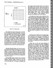
CoLUMN
to
1 2345
6zor
234 s6
7 or
234
562
ol
*oo
---'l
r
-1
LJ
ru-
*oe
o
@
@
o oo
-a_
m_
o
LE
r-
o
L'NE-L-
n-
@
roA,oB,oc,
ARE
coLUMN
couNTER
ourpurs
@o
COLUMNS
ROWS | |
tl
@
+'
!
'.1-:--------
A
---o.
Y/
'
'\i__:_'__'
o
o
(7)---.
441S120