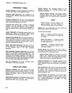
FREQUENCY
TERMS
Display
Frequency.
The
input
frequency
as
indicated
by
the spectrum
analyzer
and
expressed
i;
hertz.
Frequency
Span
(Dispersion).
The
magnitude
of
the
frequency
band
displayed,
expressed
in-hertz
or
hertz
per
division.
Frequency
Llnearity
Error.
The
error
of
the relationship
between
the frequency
of
the
input
signal
and
the fre-
quency
displayed (expressed
as
a
ratio).
Freguency
Drlft
Gradual
shift
or
change
in
displayed
frequency
over
the
specified
time
Oue
to internal
changes
in
the
spectrum
analyzer,
and
expressed
in
hertz
per
second,
where
other
conditions
remain
con-
stant.
lmpulse
Bandwldth.
The
displayed
spectral
level
of
an
applied
pulse
divided
by
its
spectral
voltage
density
level
assumed
to
be flat
within
the
pass_band.
Residual
FM
(lncidental
FM).
Short
term
displayed
fre-
quency
instability
or
jitter
due
to
instability
in
th-e spec_
trum analyzer
local
oscillators,
given
in
terms
of
pLak-
to-peak
frequency
deviation
and
expressed
in
hertz
or
percent
of
the
displayed
frequency.
Shape
Factor (Skirt
Selectivlty).
The
ratio
of
the
fre_
quency
separation
of
the
two
(60
dBi6
dB)
down
points
on
the response
curve
to
the
static
resolution
bandwidth.
Static
(Amplifier)
Resolutlon
Bandwldth.
ThE
specified
bandwidth
of
the spectrum
analyzer's
response
to a cw
signal,
if
sweep
time
is
kept
substantiaily
long.
This
bandwidth
is
the frequency
separation
of
two
points
on
the response
curyer
usually
6
dB
down,
if
it is
measured
either
by manual
scan (true
static
method)
or
by
using
a
very
low
speed
sweep
(quasi-static
method).
Zeto Pip (Response).
An
output
indication
which
corresponds
to zero
input
frequency.
AMPLITUDE
TERMS
Detlectlon
Coeflicient.
The
ratio
of
the
input
signal
rnagnitude
to the
resultant
output
indication.
Tne
ratio
may
be
expressed
in
terms
of volts
(rms)
per
division,
decibels
per
division,
watts
per
division,
or
any
other
specified
factor.
Dlsplay
Reference
Level
A
designated
vertical position
representing
a specified
input
level.
The
level
may
be
expressed
in
dBm, volts,
or
any
other
units.
Gfoesary
-
494[l4g4Ap
Service,
Vol.
1
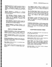
Display
Flatness.
The
unwanted
variation
of
the
displayed
amplitude
over
a specified
frequency
span,
expressed
in
decibels.
Relative
Display Flatness.
The
display ftatness
measured
relative
to the
display amplitude
at
a
fixed
frequency
within
the frequency span,
expressed
in
decibels.
Display
flatness
is
closely related
to fre-
quency
response.
The
main
difference
is
that
the
spectrum
display
is not recentered.
Display
Law.
The
mathematical
law
that
d€fines
the
input-output
function
of
the
instrument.
The
following
cases
apply:
Llnear
-
A
display in
which
the
scale
divi-
sions
are
a linear
function
of
the input
sig-
nalvoltage.
Square law
{power}
-
A
display in
which
the scale
divisions
are a linear
function
of
the input
signal
power.
Logarithmic
-
A display in
which
the
scale
divisions are
a logarithmic
function of
the
input
signal
voltage.
Dynamic
Range.
The
maximum
ratio of
the
levels
of
two
signals
simultaneously present
at
the input
which
can
be measured
to a specified
accuracy.
Display
Dynamic
Range. The
maximum
ratio
of
the
levels
of
two
non-harmonically
related
sinusoidal
signals
each of
which
can
be simultaneously
meas-
ured on
the screen
to a specified
accuracy.
Frequency
Response.
The
unwanted
variation of
the
displayed
amplitude over
a specified
center
frequency
range,
measured at
the center frequency,
expressed
in
decibels.
Gain
Compresslon.
Effect seen
at an
input
level
where
the analyzer
circuits
have less
gain
than
their small sig-
nal
values.
This is
usually specified
at
the
1
dB
compression
point
in
terms
of
the input
level required
to
reduce
the
gain
by 1
dB.
Input
lmpedance.
The
impedance
at
the desired input
terminal.
Usually expressed
in
terms
of
vswr, return
loss,
or other
related
terms for low impedance
devices
and resistance-capacitance
parameters
for high
impedance
devices.
I
o
o
O
a
o
O
o
o
o
o
I
o
o
t
o
I
a
o
o
o
o
o
o
o
o
t
O
t
o
o
o
o
o
o
O
o
I
a
o
o
o
I
o
A-2


