o
o
o
I
o
o
o
o
o
o
o
c
I
o
o
o
o
o
a
o
I
o
o
)
o
o
o
o
I
o
?
o
a
o
O
o
o
I
o
o
a
o
I
o
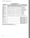
Specification
_
494A1494Ap
Service,
Vot.
1
Tabte
2-2
(Continued)
AMPLITUDE
RELATED
CHARAiTERISTICS
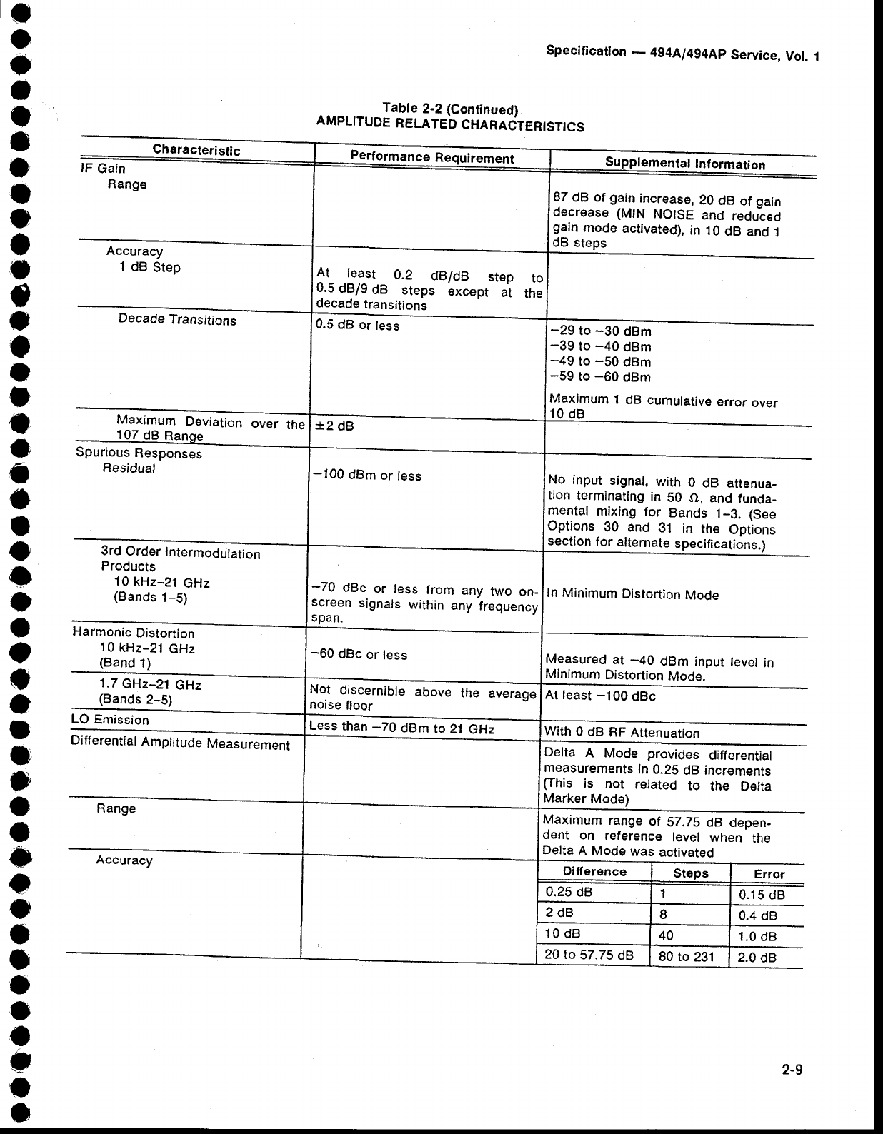
Characteristic
lF
Gain
Range
Accuracy
'l
dB
Step
..--
Decade
Transitions
Maximum
Deviation
107
dB
Range
Spurious
Responses
Residual
the
3rd
Order
Intermodulation
Products
10
kHz-21
GHz
(Bands
1-5)
Harmonic
Distortion
10
kHz-21
GHz
(Band't)
't.7
GHz-21
GHz
(Bands
2-5)
LO
Emission
-
Differential
Amplitude
Measurement
Range
Performancq
Requirement
emehlrl lnfarnari
87
dB of
gain
increase,
20
dB
of
gain
decrease
(MlN
NOISE
and
reduled
gain
mode
activated),
in
10
dB
and
j
dB
steps
lt_ ielst
0.2
dB/dB
step
to
0.5
dB/g
dB
steps
except
at
the
decade
transitions
-29
to
-30
dBm
-39
to
-40
dBm
-49
to
-50
dBm
-59
to
-60
dBm
Maximum
1
dB
cumulative
error
over
10 dB
0.5
dB or
less
*2
dB
No
input
signal,
with
0
dB attenua_
tion
terminating
in
50 O,
and
funda_
mental
mixing
for
Bands
1_3. (See
Options
30 anO
gl
in
the
Options
section
for
alternate
specifications.)
In
Minimum
Distortion
Mode
-100
dBm
or
less
-70
dBc
or
less
from
any
two
on_
screen
signals
within
any
frequency
span.
-60
dBc
or
less
Measured
at
-40
dBm
input
level
in
Minimum
Distortion
Mode.
Not
discernible
above
the
average
noise
floor
At least
-100
dBc
Less
than
-70
dBm
to 21
GHz
With
0 dB
RF Attenuarion
Delta
A Mode
provides
differential
measurements
in
0.25
dB increments
(This
is
not
related
to
the
Delta
Marker
Mode)
Maximum
range
of
SZ.7S
dB
depen-
dent
on
reference
level
when
the
Deita
A
Mode
was
activated
Ditference
Steps
Error
0.25 dB
1
0.15 dB
2dB
I
0.4 dB
10
dB
40
1.0
dB
2.0
dB
20
to
57.75
dB
80 to
231
2-9


