


Theory
of
Operation
-
4g4A/494Ap
Service,
Vot.
1
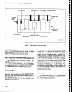
Directional
Filter
The
Directionat
Fitter
(FL10)
couptes
the 2072
MHz
signal
to the 2nd
Converter
via low-pass
and
band-pass
filters
FLl1
and
FL14.
As
mixing products
iass
through
FL16,
they induce
a selected
current
into
a
one-wavelength
distributed
dng,
which
couples
the
2072
MHz lF
signat out
to
the tow-pass
fitter
FLl
t. The
remainder
of
the intermodulation
products
pass
on
through
since
the
ring is
excited
only
with
ZiOZZ l/r{z
signals.
The
bandwidth
of
this
Dirirctional
Fitter
is
approximately
45
MHz.
The
unfiltered
signals
are
passed
on
to
the Diplexer.
o
o
o
o
O
o
o
o
o
o
o
O
o
o
O
o
o
o
o
o
o
o
o
o
o
o
o
o
o
o
a
o
o
o
o
o
o
o
o
o
o
o
o
o
7-6
2072MHz lF
Filters
The 2072 MHz
signal,
from
the
Directional
Fitter,
passes
through
a 4.5
GHz Low-Pass Filter
{FL11}.
The
signal
is
then
sent
through
a 15
MHz band-pass
filter
(FL14)
which reiects
intermodulation
products
either
side
of
the
2072
MHz lF.
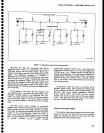
Diplexer and Filter
The
Diplexer
(A14)
passes
the 829
MHz
tF signal
from
the
mixer output
through a low-pass filter (FL15)
to
the 2nd
Converter. The Diplexer
and Directional
Filter
provide
a broadband impedance
match to the l st
Mixer
lF
port.
This match contributes
to thE
overall
flatn€ss
and
frequency response
of
the analyzer.