


a
I
o
o
o
o
o
I
o
o
o
t
o
t
o
I
I
I
o
a
a
o
o
o
o
o
t
o
o
O
a
o
o
a
o
o
I
t
o
o
a
o
o
o
.
f.
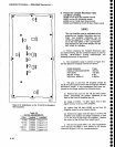
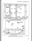
Adjust
Band
2
Gain
RgOg4
on
th€ vR
Mother
b.oard #2
(Figure
5-241
tor
a
fult
screEn
(_20
OBml
display.
_
g.
Chang€
th€
FREQUENCY
RANGE
to
3.0_
7.1
GH.z
(Band
3) and
appty
a catibrated
_20
dBm
sig-
nal
with
the
same
frequency
as
noted
for
the
mean
level
in Band
3
for
part
a of
this
step.
h.
set
the FREQUENCy
to
the
incoming
signat
and
FFEO
SPAN/DIV
to
500
kHz/Div
i. Adjust
Band
3 Gain
R3030
(Figure
5-24)
for a
futl
screen
display.
j.
Repeat
the above
procedure
for
€ach
coaxial
band
(1-5)
and
set
the
gain
of
each
with
the appropri-
ate
adjustment.
lf
the
range
of
any
adjustmEnt
is
insufficlent,
add
or
r€move
a
diode
betrr,leen'pin
DD
and
th€
-appfopriate
adjustment
potentiometer
on
th€
vR
Mother
board
#2.
to
obtain
the reguired
range.
Refer
19 .th:
schematic
diagram
and
component
tocator
for
Variable
Besolution
Mother
goarOs,
in
Volume
2.
Adding
the
diode
increases
gain.
15.
Adiust
Band
Leveling
for
Waveguide
Bands
(Bands
6-11)
(R3024,
R3026,
Rg02g,
R9029,
anct
R3032
on
the
VR
Mother
board
#Z)
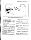
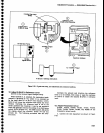
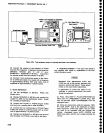
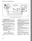
?. I:g!
equipment
setup
is
shown
in
Figure
5-23.
Apply
2072
MHz
at
-€O
dBm,
through
a
dt_btocking
capacitor
to the
EXT
MIXER
input.
Monitor
the inpui
with
a
pow€r
meter
to
set
the
pow€r
tevel
then add
a
known
30
dB
attenuator
so
th€
input
level
to
the
EXTERNAL
MIXER
port
is
-60
dBm.
'Set
ttre
Spectrum
Analyzer
controls
as
follows:
FREQUENCY
RANGE
1g_26
GHz
(Banct
6)
FREO
SPAN/D|V
200
MHz
AUTO
RESOLN
On
REF
LEVEL
-3OdBm
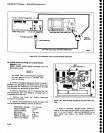
The
baseline
of
the
display
will
rise
when
the
2072
MHz
signat
is apptied
to
the
EXTERNAL
MTXER
input
port
connector.
b. With
-60
dBm input
level
apptied,
adjust
Bancl
6
Gain Leveting
R3024
(Figure
5-24)
lor iuil
screen
display.
c.
change
the FREQUENCY
RANGE
and
input
sig-
nalfrequency
and
level
as
listed
in
Table
54, and
adjuit
the appropriate
Band
Gain
adjustments
for a
fult screen
display.
Gain
adjustment
for
the waveguide
bands
need
to
be adjusted
only
if
these
bands
will
be used.
d. Switch
POWER
off;
replace
Variable
Resolution
module,
then
switch
POWER
back
on.
Adru3tment
Procedure
-
4g4rl4g4Ap
Service
Vot.
I
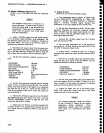
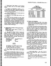
Tabte
5-4
EXT
MIXER
BAND
LEVELING
ADJUSTi,IENTS
Band
Gain
AdJustment
6
(18-27
GHz)
7
(26-40
GHz)
8
(33-60
GHz)
9
(50-90
GHz)
10
(75-140
GHz)
11
(110-220
GHz)
12
(r7O-325
GHz)
R3024
R3026
R3032
R3029
R3028
R3028
R3028
16.
Phase
Lock
Calibration
(C1016,
C1018,
C1032, and
C1034
on
the
Strobe
Driver
board;
C10i3 and
C2011
on
th€
Controlled
Oscillator
board;
and
Rl06l
and
R3Og2
on
the Error
Amplifier
board)
The
Phase
Lock
assembly
normally
requires
calibra-
tion
only after
some
part
of
the assembly
has
been
repaired
or
replaced.
phase
noise,
produced
by
the
phase
lock loop,
is specified
tor
-7AdBc
or
better,
3
kHz
out from
the
response.
This
should
be checked
before
calibrating
th€ assembly.
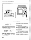
a.
Test equipment
setup is
shown
in Figure
5-25.
Remove
the
Phas€
Lock
module
and
the two
cover
plates
so all
circuit
test
points
and adjustm€nts
are
accessible.
Plug
the assembly
on extender
boards
and
into
the instrument.
Use
Extender
cables
and
adapters
to reconnect
signal
cables
to their
respective
connector
(cable
with
yellow
band
to J501, and
the
cable
with
black
band
to J502).
lf
d€sired,
the
direct reading
counter may
be con-
nected
to the Vertical
Output of
the t€st
oscilloscope
to
get
a count
of
a
display at
each
test
point,
when
appropriate,
throughout
this
procedure.
The ground
side
of
the test
oscilloscope
probe
will serv€
as
the
common ground
return
for
both
instruments.
b. Press
<Blue-SHIFT>
CAL and
do
the directed
calibration
routine
through adjusting
the
LOG
CAL.
Press
<Blue-SHIFT>
to return
the
instrument
to nor-
mal
operation
and
set
REF LEVEL
to
-30
dBm.
Check
that the
AUTo RESoLN
is active (button
tit).
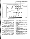
c.
Check
O{fset
Mixer
-
This
part
of
the
pro-
cedure
is only
required
after repair
or replacement
of
the
Mixer
board.
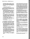
(1)
Connect
the Direct Input
of
the frequency
counter
to
pin
N
(Figure
5-26) and set the counter
controls
for a
count.
Note
the
frequency.
(2)
Connect
the
counter
to
pin
K and
note
the
fre-
quency.
5-25