


Performance
Check
procedure
-
4g4A/4g4Ap
Service
Vol.
1
Spactum
Analtrar
Un(br
Totl
al|C
T{oilt clot
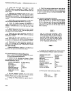
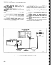
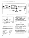
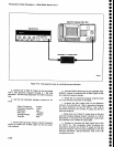
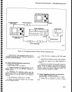
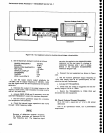
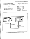
Figure 4'16.
Test
equlpment
setup
for
checking intermoduration
distortion.
o
o
t
o
a
o
O
a
o
I
o
I
o
a
o
I
I
a
o
t
o
o
o
o
o
o
o
o
o
o
t
o
o
o
t
I
C
a
a
O
o
o
o
o
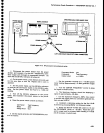
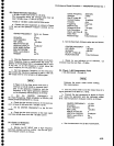
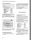
freq.-..t,
f1
t2
Third
(3rd)
Order Intermodulation
products
2127_.ts
Figure
4-17.
Intermodulatlon
products.
b. Set
the
generator
outputs approximately
2
MHz
apart
within the
frequency
range of
band
1, and
set the
output
levels for full
screen
signals.
c.
Decrease
the separation
of
the
generator
fre-
quencies
to 1 MHz.
Reset
the spAN/Dlv
to
500 kHz
And
RESOLUTION BANDWIDTH
to 1O KHz.
d. Check
that
the
third
order
lM
products
are at
least
70 dB
down trom
the input signal level.
See Fig-
ure 4-17.
Use
the Video
Filter
and
very
slow sweep
rates
to help resolve
these
sidebands.
e.
Decr€ase
the signal
separation and
SPAN/DIV
settings and
re-check
for sidebands.
Check
for
lM
pro-
ducts at olher
spans
of
the
frequency
range.
lM
pro-
ducts
should
be
-70
dBc or more.
f.
Change the FREQUENCY
RANGE
to Band 2
(1.7-5.5
GHz),
FREQ
SPAN/DIV
to 5
MHz,
and RESO-
LUTION
BANDWIDTH
to 100
kHz.
g.
Reset
the
generator
outputs approximately
2 MHz
apart within
the
frequency
range
of
band 2, and
set
the output levels
for full
screen
signals. Reduce
the
SPAN/DIV
and
RESOLUTION
BANDWIDTH so
the noise
floor is
at
least
70
dB
down from
the
reference
level.
h.
Check that lM
products
are
at least 70
dB down
from
the
input signal
level or
top
of
the
screen.
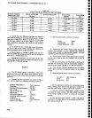
22.
Check
Intermodutation
Distortion
fl-hird
order
products
at least
70
dB
down from
anv
two
on-screen
signals)
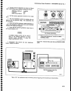
a.
connect
the
test equipment
as
shown
in
Figure
4-16, and
set
the
Spectrum
Analyzer
controls
as
fol-
lows:
FREO RANGE
CENTER FREQUENCY
sPAN/DrV
RESOLUTION
BANDWIDTH
REF LEVEL
MIN
RF ATTEN
dB
VERTICAL
DISPLAY
TrME/DrV
4-28
0-1.8
(Band
1)
Within
2 MHz
of
Test
Generators
5 MHz
100
kHz
-30
dBm
n
10
dBiDrv
AUTO