


Theory
of
Operaton
-
494A/494Ap
Service,
Vol.
1
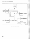
The
Frequency
Control section performs
the tuning
and scan
function
for
the
preselector,
l st
LO, and 2nd
LO.
lt also
provides
the
sweep
voltage
for
the
deflection amplifiers
in
the Display
section
so
the
crt
display
is
coincident
with
the frequency
scan and
tun-
ing. This
section
contains
the following
major circuits.
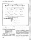
Sweep
Circuits
on
the
Sweep
board
accept
trigger
inputs
from
line,
internal and
external
sources,
and
the normal
free-run
mode
of
operation.
They
also
receive
external
horizontal and
manual
sweep
inputs.
The
circuits
pro-
duce a PEN
LIFT
signal
for
ehart
recorder
applications,
a
SWEEP
GATE
signat
for crt
disptay
btanking, a
SWEEP signalto
drive
the crt
beam across
the
horizon-
tal axis
and drive
the horizontal portion
of
the digital
storage
circuit.
plus
a ramp (OSC
SWEEP)
that is fed
through
the Span Attenuator
to the
preselector
Driver.
the 1st LO
Driver,
and
the 2nd
LO.
Span Attenuator
This circuit attenuates
the ramp
signal as
required,
to
swe€p
the
frequency
of
the
'lst
and 2nd
tocal
oscilla-
tors,
and
tune the Preselector
so
it
tracks the
center
frequency.
Center
Frequency
Control
The Center
Frequency
Control
circuit
provides
a
tun-
ing voltage
for
the 1st
and
2nd
Local
Oscillator circuits
that
results in a
linear
center
frequency
change as
the
front
panel
FREOUENCY
control
is changed.
The
cir-
cuit is
directly controlled
by
the microcomputer,
so
remote control of
the frequency
is
possible,
by way of
the cPlB rear-panel
connector.
The
COARSE TUNE
VOLTS
signal
from
this
circuit
is applied
to
the 1st LO
Driver circuits for
summing
with
the
SPAN
signal
to
drive
the
lst LO.
The
FINE
TUNE
VOLTS
signat is
applied
to the
Preselector
Driver
for summing
with
the
lF
Offset voltages, and
to the 2182
MHz
phase
Locked
2nd
LO circuit for
summing
with
the
2nd
LO
SWEEP
signal.
l
st
LO Driver
The
1st LO Driver
performs
the following:
o
Combines the
COARSE
TUNE
VOLTS signat
with
the sPAN
signal
and
outputs
a current
to
drive the
1st LO.
.
Produces the
tuning
and sweeping
signal for
the
Preselector Driver
circuits.
I
Produces the mixer
bias
voltages.
o
Produces a reference
voltage
that
is
used
in
both
the
1st
LO
Driver circuit and
the
Pres€l€ctor
driver.
o
Produces a supply voltage for
the 1st LO.
Preselector Driver
The Preselector
Driver combines
the FINE TUNE
VOLTS
signal,
from
the Center
Frequency
Control
board
with
the PRESELECTOR
DRIVE signal and
the SPAN
VOLTS
signal lrom
the
l st LO Driver.
This
combined
signal is offset, to
compensate lor
the selected
l st
lF,
then shaped so the Preselector tracks
with
the
lst
or
2nd Lo as it is
tuned by the
output current. The
Preselector
Driver also
drives the
Filter
Select
switch
that
selects
either
the Preselector or
the
Low-pass
Filter, depending
on
the
frequency
band
selected.
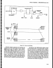
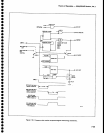
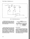
SWEEP
(Diagram
31)
The circuits
on
the Sweep board
(A72)
provide
the
ramp voltage that
drives the
horizontal deflection
amplifier,
the
l
st
LO Driver, the Preselector
Driver,
the
2nd LO, and
a voltage
used
to
align
the
frequency
con-
trol
system with
the digital
storage
marker
positions.
The sweep
board
also
provides
signals
for the Z-Axis
circuitry, an external
plotter pen,
and digilal storage.
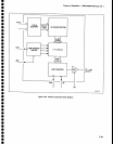
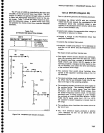
The major
circuits on the
Sweep board
are:
o
Sweep
Generator
.
Trigg€r
Circuits
.
Sweep
Control
o
DigitalControl
o
Marker
DAC
The sweep
generator generates
the
voltage
ramp
that drives the
Deflection Amplifiers,
Digital Storage,
Preselector,
and the
swept oscillators.
The trigger
circuits
proc€ss
and multiplex the
three
trigger
signals.
The sweep
control circuit
generates
the
SWEEP
GATE
and PEN LIFT signals
and
determin€s
the
holdoff
time tor the sweep
generator.
FREQUENCY
CONTROL
SECTION
(Diagram
7)
o
o
o
o
a
o
O
o
o
a
o
o
o
a
o
o
o
o
o
O
o
t
o
a
o
o
o
o
o
a
o
o
O
o
o
o
o
o
o
o
o
o
o
o
7-60