


I
o
o
O
a
o
o
t
o
o
I
,
o
o
o
o
a
t
t
o
I
o
a
o
o
O
a
o
a
I
o
I
o
O
t
O
I
o
o
o
o
o
I
o
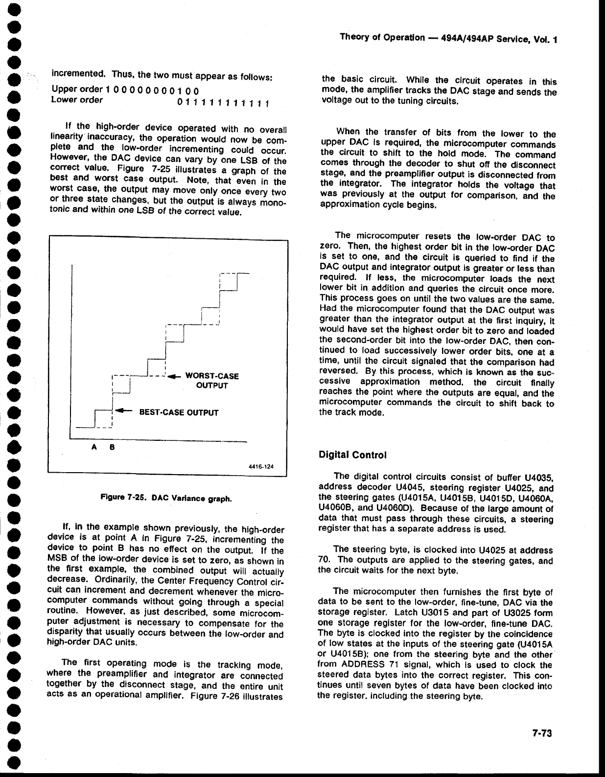
lf
the high-order
device
operated
with
no
overatl
linearity
inaccuracy,
the
operation
would
now
be com-
plet€
and
the
low-order
incrementing
could
occur.
However,
th€ DAC
device
can
vary
byine
LSB
of
the
correct
value.
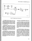
Figure
7-25
illustrltei
a
graptr
of
the
b€st
and
worst
case
output.
Not€,
that-even
in
the
worst case,
the
output
may
move
onty
once
every
two
or
three state
changes,_but
the outpuf
is
always
mono_
tonic
and
within
one
LSB
of
the correct
value.
incremented.
Thus,
the
two must
appear
as
follows:
Upperorder
1
0
0 00
0
O
O
O 1
0 O
Lower
order
01'l
111111111
Theory
of
Operation
-
4g4Ll4g4Ap
Servlce,
Vol.
1
the
basic
clrcuit.
Whil€
the
circuit
opgrates
in
this
mod€,
the
amplifier
tracks
the DAC
stage
and
sends
the
voltage
out
to the
tuning circuits.
When
the transfer
of
bits from
the lowgr
to the
upper
DAC
ls
required,
the microcomputer
commancls
the circuit
to shift
to
the
hold
mode.
Th€
command
comes
through
the decoder
to shut
off
the
disconnect
stage.
and
the
preamplifier
output
is
disconnected
from
the
integrator.
Th€ integrator
holds
th€ voltage
that
was
previously
at
the output
for
comparison,
and
the
approximation
cycle
begins.
The
microcomput€r
resets
the
low-order
DAC
to
zero.
Then,
th€
highest
order
bit
in
the
low-order
DAC
is set
to one,
and
th€ circuit
is
queried
to
find if
the
DAC
output
and integrator
output
is
greater
or less
than
required.
lf
less.
the microcomput€r
loads
the
next
lower
bit
in addition
and
queries
the
circuit
once
more.
This
process
goes
on
until
the
two
values
are
the same.
Had
th€
microcomputer
found
that
the DAC
output
was
greater
than
the
integrator
output
at
the
first
inquiry,
it
would
have
set
the
highest
ordEr
bit
to zero and
loaded
the second-order
bit
into
the
low-order
DAC.
then con-
tinued
to load
successively
lower
order
bits,
one
at
a
time,
until
the
circuit
signaled
that
the
comparison
had
reversed.
By
this
process,
which
is known
as
the
suc_
cessive
approximation
method,
the circuit
finally
reaches
the
point
where
the outputs
are €qual,
and
th6
microcomputer
commands
the
circuit
to shift
back
to
the
track
mode.
Digital
Control
The
digital control
circuits
consist
of
buffer U4Og5,
address
decoder
U4045, steering
register
U4025, and
the steering
gates
(U4015A,
U40158,
U401SD,
U4O6OA.
U4060B,
and
U4060D). Because
of
the
large amount
of
data that
must
pass
through
these
circuits, a steering
register
that
has a
separate
address
is
used.
The
steering
byte, is clocked
into
U402S
at addr€ss
70.
The
outputs
are applied
to the
steering
gates,
and
the circuit
waits
for the next
byte.
The
microcomputer
then furnishes
the
first
byte ol
data
to
be sent
to the low-order.
fine-tune,
DAC via
the
storage
register.
Latch u3015 and
part
of
U3025
form
one
storage
register
for the low-order,
fine-tune DAC.
The
byte
is clocked
into
the
register
by the
coincidence
of low states
at
the inputs of
the steering
gate
(u4015A
or
U401
5B);
one
from
the st€ering
byte
and
the
other
from ADDRESS
71
signal,
which
is
used to
clock
the
steered
data bytes into
the
correct
register.
This con-
tinues
until seven
bytes of
data have
b€en
clocked into
the
register.
including
the
steering
byte.
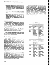
Figure
Z-2S.
DAC
Varlance
graph.
ff,
In
the example
shown
previously,
th€
high-order
device is at
point
A in
Figure
7-25,
incrementing
the
device
to
point
B
has
no
effect
on
the output.
lf
the
MSB
of
the low-order
device
is
set
to zero,
as
shown
in
the first
example,
the combined
output
will
actually
de.crease-
Ordinarily,
the
Center
Frequency
Control
cir-
cuit
can
increment
and
decrement
whenever
the
micro_
computer
commands
without going
through
a special
routine.
However,
as
just
described,
some
microcom-
puter
adjustment
is
necessary
to
compensate
for
the
disparity
that
usually
occurs
between
the
low-order
and
high-order
DAC
units.
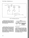
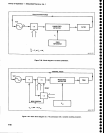
The first
operating
mode
is
the
tracking
mode,
where
the
preamplifier
and
integrator
are
connected
together
by
the
disconnect
stage,
and
the
entire
unit
acts as
an operational
amplifier.
Figure
Z_26
illustrates
t-
--;
il
WORST-CASE
OUTPUT
-r-]*-
BEST.CASE
OUTPUT
Mr6.124
7.73