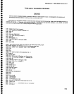
Data
Blts
76549210
D.
Digital
Storage
(cont)
DB7-DBO
DB7-DBO
x1'lxxxxx
xl0xxxxx
x0lxxxxx
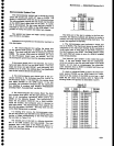
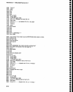
E. Z-Axls
& RF
Interfaee
Maintenance
-
494A^l494Ap
Service
Vot.
1
Table
&13 (cont)
Table
&13
{cont)
Deseription
Ver$cal
Digltal
Storage
Board
FA
Data
values
from
digital
storage.
A
write
to 78
initializes
output
to
begin
at
the
left
of
the
trace
and
proce€d
to
the
right
FB
Always
high
to indicate
that
it is
frorn
the
Vertical
Digital
Storage
board
7A
Data
values
for
digital
storage.
A write
to
78
clears
the
address
counter
so
values
are
stored
for
points
on
the
display
starting
at
the left
and proceeding
to
the
right
in
order
7B
Peak/Average
cursor
in
knob
position
Peak/Average
cursor
in
peak
position
Peak/Average
cursor
in
Average
position
Max
Hold
on
Max
Hold
off
Z-Axis
& RF
Attenuator
{4F)
Baseline
clipper
on
Baseline
clipper
off
0
dB
RF
attenuation
10
dB
RF
attenuation
20
dB
RF attenuation
30
dB
RF
attenuation
40
dB
RF
attenuation
50
dB
RF
attenuation
60
dB
RF attenuation
829
MHz
2nd
converter
2
GHz
2nd
converter
EXT
MIXER
RF
INPUT
100
ms
to switch
attenuator
Power
Supplies
Status (CF)
Fault
Supplies
okay
lxxxxxxx
0xxxxxxx
xlxxxxxx
x0xxxxxx
xxlxxxxx
xx0xxxxx
xxxxlxxx
xxxx0xxx
xxxxxxlx
xxxxxxOx
xxxxxxxl
xxxxxxx0
D84
oB2
Data
Eits
76543210
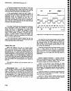
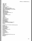
F.
Crt Readout
DB7.DB6
DB5-DBO
D87
DBO
DB5-DBO
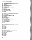
G.
Sweep
Extended
Address
1 and
Address
2
Crt Controt
(5F)
Spectrum
chop
enable
Spectrum
chop
disable
32
characters/line
40
characters/line
2lines
16lines
Max
span
dot
on
Max
span
dot ofr
Address
2F contains
an
address
Address
2F
contains
data
Readout
enabted
Reaclout
disabled
to
load
readout
A8
(address
bit
8)
A9
(address
bit
9)
Address/Data
(2F)
lfDBlin5F-1-A7,A6of
address.
With
Ag and
A9 in
5F,
they
specify
the line
number
(0-F).
lf DBI
in5F-1
A5-40
of
address.
This
specifies
the character posi-
tion
in a
line.
lf
DBl
in5F-0
1
-
Character
is a
space
0
-
Character
is not
a space
lf DBl
in5F-0
1-Skipaline
0:
Don't
skip a tine
lf DBl
in
5F
:0
Character
code
(lower
6 bits
of
ASCII)
1F
Extended
Address
1
Extended
Address
0
Marker
DAC/Ramp
Generator
Trigger
Single
Sweep
Disable
Sweep
Gate
Disable
Trigger
Abort
Sweep
Subaddress
bits
for
Port
0F
giv-
ing
subaddresses
3-0.
Subad-
dresses
0 and
t
have
the
rest of
the
control
bits
not
on Address
lF.
Subaddresses
2 and
3
receive
the 12
bits to set
the
DAC.
xxx'txxxx
xxx0xxxx
lxxxxxxx
xlxxxxxx
xxlxxxxx
xxxxlxxx
xxxxxlxx
xxxxxxlx
xxxxxxxl
lxxxxxxx
0xxxxxxx
x1xxx1x1
x1xxx1x0
x0xxx1x1
x1xxx0x1
x1xxx0x0
x0xxx0x1
x0xxx0x0
xxlxxxxx
xx0xxxxx
xxxlxxxx
xxx0xxxx
xxxxOxxx
xxxxxxlx
xxxxxx0x
6-59


