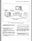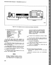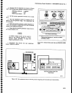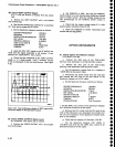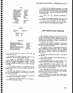
32.Gheck
Option
07
Frequency
Response
(Response,
about
.
tt"'
rniJioini'.0!i*""n
two
€xtremes,
measured
with
10
dg
oi
nF-ettenuation,
is
*2
dB
from
S
MHz
to
1000
MH;i
farts.lt-trryugh
f
check
frequency
response
fro.m
t0
MHz
to
1
GHz,
anO'partJ
g
il;;;;
i;ff;:.t*ouency
response
from
6
Mllii"
Performance
Check
procedure
_
4g4Ll4g4Ap
Service
Vol.
1
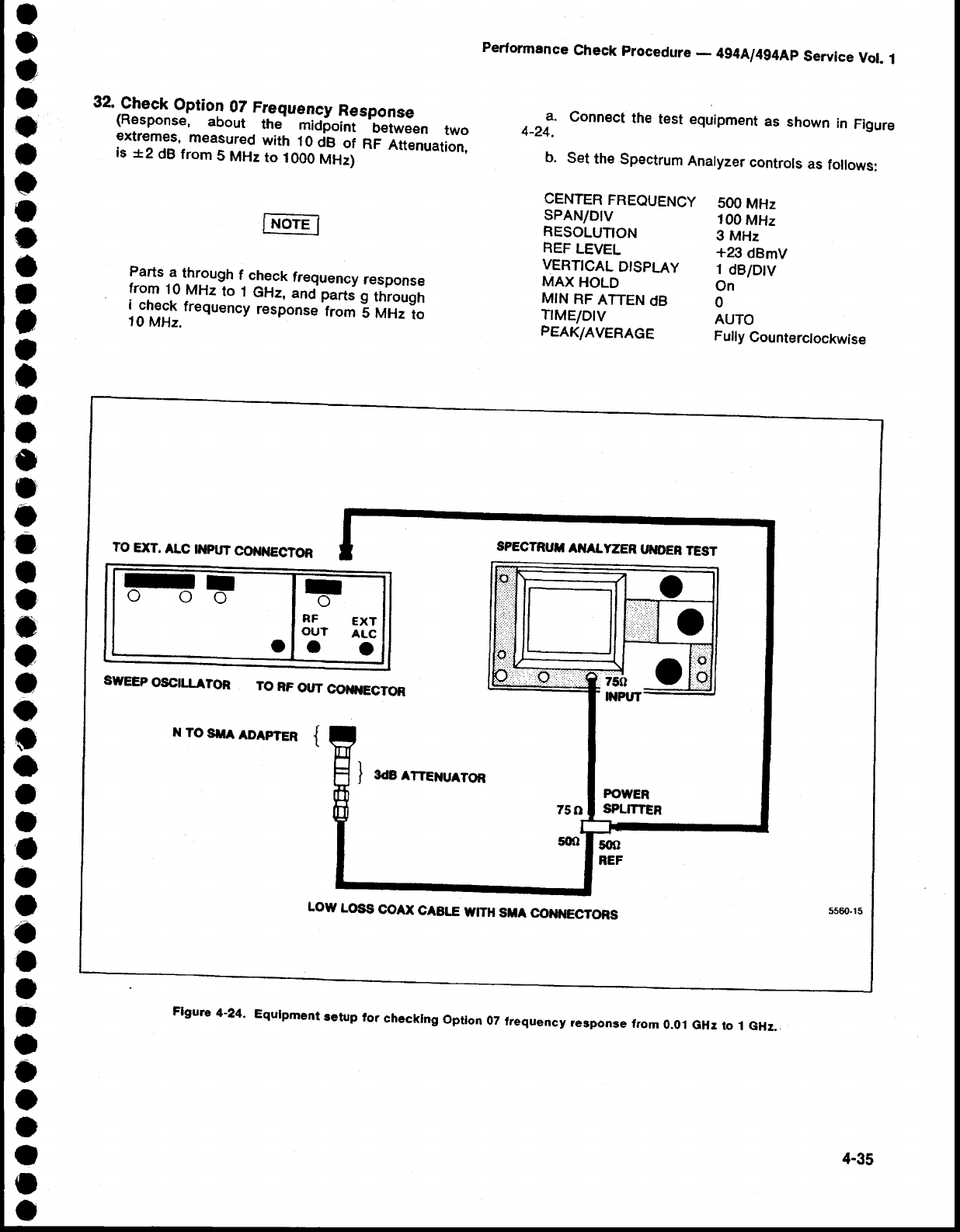
a.
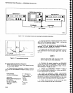
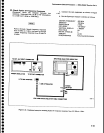
Connect
the
test
equipment
as
shown
in
Figure
4-24.
b.
Set
the
Spectrum
Analyzer
controls
as
follows:
CENTER
FREOUENCY
SPANIDIV
RESOLUTION
REF
LEVEL
VERTICAL
DTSPLAY
MAX
HOLD
MIN
RF
ATTEN
dB
TrMElDlv
PEAK/AVERAGE
500
MHz
100
MHz
3
MHz
+23
dBmV
1
dBiDtv
On
0
AUTO
Fully
Counterclockwise
TO
EXT.
ALC
tilpUTCo0$ttECTOn
I
oo
I
o
I
o
RF
ExT
OUT
ALc
ot
a
o
SPECTRUII
AiIALYZER
UilOEF
TEST
SWEEP
OSCILLATOR
TO
RF
OUT
COI{}{ECTOR
r{TOSIIAADAPTER
{
POWER
SPLITTER
5G)
REF
LOW
LOSS
COAX
CABTE
WITH
SUA
CONilECTORS
5560.15
Flgure
4-24'
Equlpment
retup
for
checklng
option
0z
trequency
?esponse
from
0.ol
GHr
to
1 GHz.
4-35


