


o
o
o
t
o
t
t
o
o
a
:
t
o
o
o
I
a
o
3
a
o
a
o
a
t
o
o
o
o
o
o
o
I
o
a
o
o
o
o
o
a
o
o
o
the
500
digital
storage
sweep positions.
The
resulting
clisplay
appears
as
a
bright
dot
sweeping
across
the
crt,
rising
and
falling
with
the
signat.
The
basic
circuits
consist
of
a
set
of
latches,
a
digital-to-analog
convert€r,
a
compar"toi,
"
pulse
gen_
erator,
and
control
circuitry.
The
Horizontat
Disptay
[iD)
data represents
thE
ligital
equivatent
ot
the
pi"ieni
update
position.
The
latches
cipture
the
data,
and
the
digital-to-analog
converter
{dac)
converts
it,
creating
the
analog
horizontal
deflection
signat.
When
the
swe€p
voltage
reaches-
the
dac
level,-the
sw€ep
stops
for
a longer period
of
time,
and
therefore
the crt
is
brighter,
than
at
other
sweep
positions.
On
the next
sweep,
the
HD
data
increments
to
the next
position,
rnoving
the
cursor
along
the
sweep.
... Th"
DSPL
EN (Disptay
Enabte)
signal
ctocks
the
HD
(Horizontat
Oata)
signats
into
latctres'Ul020
and
U2O3O.
The
tatch
outputs
drive
U2020,
a
1O_bit
oilitat+o_anatog
converter.
The
converter's
output
currenidrives
operai
tional
amplifier
U4029A, producing
,a
voltage
called
HORIZ
StG.
When
a
digitat
storagJsignat
is
disptayed,
HORIZ
SIG
drives
the
horizontat
O-eReciion
nmpliiier.
.
Also,
U196-O
compares
HORIZ
StG
to
the
sweep
vol-
tage
from
U40Z9B.
The
comparator
output
drives
the
"Updat€
lnt€nsity.
input
on
the
Marker
tC,
U30eO.
*re
tularker
tC
Aenerates
"
l-6_-g!it
putse,
ctocied
by
DSpL
5N..Ll"_-ri:'.!g
edge
of
U3O2O';
output
putse
produces
the INTENSITy
signal
that
temporaiily
prevents
count-
ing
by
the
g-bit
display
counter
'in
u5020.
This
effectively
stops
the
beam
for
a
short
time
ancl
causes
a
bright. spot
(cursor)
on
the
trace
to indicate
the horizon-
tal
point
being
updated.
Fast
Retace
Blanking.
Between
the
display
of
the
B memory
contents
and
display
of
the
A
m€mory
con-
tents, a
fast
retrace
occurs,
This
retrace,
unlike
the one
that tollows
the A
memory
display
(cursor),
is
not
required
to
be seen
and
is
blanke;.
This
is
accom-
plished_
by
btanking
control
flip_flop
U10148,
which
is
controll€d
by
the
most
significant
bit
of
the rnemory
address
and
the DSPL
EN
signat
during
a
marker
cycte.
. .
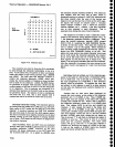
Mernoriea.
Integrated
circuits
U1026
and
U2026
pro-
vide
8k
bits
of random
access
m€mory
for
storage
of
tfie 1000
data
points
used
In
the
digitalitorage
system.
Addressing
during
bus
transfer
of
iremory
data
is
con-
trolfed
by
address
tri-state
buffers
Ul}dg
and
U1016
and
by horizontal
control
lC
U2095
during
memory
update.
Theory
of
Operaton
-
4g4[l4g4fup
Service,
Vol.
1
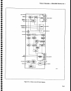
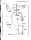
DEFLECTION
AMpLtFtERS
(Diagram
27)
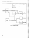
Refer
to the
btock
diagram
adjacent
to
Diagram
27
as
well
as
the schematic
diagram.
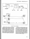
The
Deflection
Amplifier
receives
vertical
signal
information
from
the
vertical
section
of
Digital
Storage
or
the
Mdeo
proces_
sor,
and
horizontal
or
sweep
voltage
from
the
horizontal
section
of
Digital
Storage
or
the
Sweep
board.
Readout
data
for
the
display
comes
from
the
crt
Readout
cir-
cuits.
Th€
output
of
the D€fl€ction
Amplifier
drives
the
crt
deflection
plates.
The
amplifiers
contain
the switch-
ing
circuits
necessary
to
perform
th€ setection
functions
and
they also
contain
the
amplifier
stages
needed
to
produce
the
deftection
plate
drive
signats.
Horizontal
Section
Signal tines
HORTZONTAL
StcNAL (from
the
digitat
storage
circuits
through
edge
connector
pin
ag)
-and
SWEEP (trom
the
Sweep
circuit
through
edge
connector
pin
51) are applied
to
switch
lC
UZOSSA.
UZ0SS.
unOer
control
of
the
STORAGE
OFF
signal (from
the
digital
storage
circuits
through edge
connector
pin
7),
setects
either
the HORIZONTAL
STGNAL
or
SWEEp
input.
The
SWEEP
signat
is setected
wh€n
the
STORAGE
bff tine
is
floating
or
putted
high.
The
HORTZONTAL
STGNAL
is
selected
when
the
line
is
pulled
low.
Resistive
divider
R7051
and
R7081
reduces
the selected
signal
from
1 V/div
to
0.5
V/div.
UZIT!
buffers
the selectLd
signat.
It
goes
out
to
the HORIZ
OUT
rear-panel
connector
via
edge
connector pin
48.
UZoZ3
applies
the
signat
to
switch
U70558.
The
HORTZ
R/O
signat,
lrom
the
Crt
Readout
circuits,
is also
applied
to U7OS5B.
The
R/O
OFF signal,
from
the
Crt Readout
circuits
selects
between
th€s€
two
signals.
When
R/O
OFF is floating
or
pulled
high,
the switch
transmits
the signal
from
buffer
U7073
to
the
shaper.
When
the
line is
pulled
low,
it
selects
the
HORTZONTAL
R/O
signal.
U70558
applies
the
signal
to a shaper
network
to
comp€nsate
tor
non-linearity
in
the
crt
deflection
characteristics.
This
network
consists
of
resistors
R5059,
R5058,
R5057,
RS062,
R4061,
and
R4059,
ptus
diodes
CR1012,
CR4051,
CR4OS8,
and
CR4056. The
HORIZONTAL
POSIT|ON
vottage,
from
the front
panet
via
edge
connector
pin
47,
through resistor
R6032,
is
applied
to
the
shaper
circuit
so
the shape
correction
factor
relates
to the crt
deflection.
The
shaped
signal
is
then applied
through
preamplifier
U2060
to
the
deftection
amplifier
circuits.
Horiz
Gain
adjustment
Rl0S5,
calibrates
th€ amount
of
gain
compensation
required
for
proper
deflection
sensi-
tivity.
The
horizontal
d€flection
amplitier
consists
of
two
circuits
similar
to each
other,
one
for each
horizontal
deflection
plate.
One circuit
is an inverting
amplifier,
the
other
operates
in-phase.
Inputs
to
e4oggA of
the
invert-
7-47