


O
o
o
o
o
o
o
o
o
o
o
a
o
o
o
o
o
o
o
o
O
o
o
o
o
O
)
o
a
o
o
o
t
o
o
o
o
o
O
o
o
o
o
o
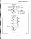
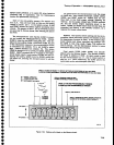
will
see
a
phantom
closure
at
y2lxg
as
it
scans
the
key
matrix.
To
suppress
these
piantom
key
closures,
diodes
have
been added
in
series
with
the RESOLU-
noN
BANDWTDTH,
MtN
RF
ATTEN,
SpAN/D|V,
and
gerta]l
other
keys in
column
6
and
7
of
the k'ey
matrix.
In
addition,
an €rror
detection
algorithm
is
used
in
the
CPU
to eliminate
additional
ptraniom
key
closures
that
might occur.
_
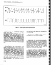
scanntng
the FREoUENCy
controt
coder.
The
FREQUENCy
control
contains
a
pair
of
phototransistors
that
outpul
a
gray
code
through
Ut024Ei
and
U1024C
to
P27.
and
p26
(pins
37 and
36; ot
the
CpU.
This
gray
code
signifies
the direction
the
control
is
turned.
Ou-rini
a
scan
cycle,
the GpU
looks
at
th€ status
of
the FRE-
QUENCY
control
code
and
if
it
detEcts
a change,
the
CPU
performs
a shift
and
exclusive,OR
operation
which
derives
the correct
code
to output
ouer
ihe instrument
bus
to
the
master
processor
to tell
it
which
direction
to
tune
the center
frequency.
Outputting
the
Correct
Code.
The
remaining
two
bits.out
of
port
2
(pZ4
and
p25)
drive
the
appropriate
hardware
and
initiate
an
SRe
on
the
instrument
bus.
When
th€
SER
REe
line
is
pulled
down,
the
master
microprocessor
will
service
either
the
keyboard
or
th€
fre-quency
coder.
The
front
panet
CpU
(Uir0gg)
initiates
a
SRQ
by
putting
down
p24
or
p2S.
A tow
out
ot
pZ4
(pin
35) wilt
initiate
a
keyboard
SRe.
The
master
microprocessor
will
now
service
the request
by reading
the keyboard
data in
output
buffer
U4$b.
A
low
out
ol
P25
(pin
36) initiates
a
FREQUENCy
controt
SRe
and
causes
the
master
microprocessor
to
service
the
request
by reading
the frequency
code
in the
output
buffer.
A
low
out
ot
p24
is
inverted
by
U2020C
so it
clocks
the
flip-flop
Ug013B.
The
resultint
low
on
the
e(bar)
output
puils
the
sER
REQ
tine
down. (Refer
to
thg
instrument
bus
POLL
sequence
described
under
the
master
microprocessor
description
for
the service
request
sequence.)
The
master
microprocessor
now
raises
both
the POLL
tine
and
ABZ.
This
is
gated
through
u4014A
as
a
low
to DBo
on
the instrument
bus.
The
master
microprocessor
reads
the
bus
and sees
a
low
on
DB0.
This indicates
that
a
keyboard
interrupt
has
occurred
and
it
must
read
the
new
kevboard
code.
The
master
proeessor
first
clears
the
interrupt
by
pul-
ling
AB7
and
then
the
POLL
tine
tow.
DBO
now
goes
high.
The
master
microprocessor
now
writes
a
0 to
DBo,
the
same
as
it
read,
and
raises
the
pOLL
line.
This clocks
U3013A
and
resets
Ug0138
which
removes
the
SRQ(bar).
The
instrument
processor
now
reads
the
data in
the output
buffer,
U4Og0,
at
address
F4.
The
front
panel
CPU
now
recognizes
that
its
output
buffer
has
been read
and
it resets
p24to
a
1.
lt
is
now ready
Theory
of
Operation
-
4g4[l4g4Ap
Service,
Vol.
1
for
another
cycle.
A similar
process
occurs
when
p25
(pin
36) of
the
CPU
is
p_u!l9d
low
by a
FREQUENCy
coder
inteirupt.
A
!9y
on P25
is
propagated
through
UZ02OB,
U20t3A,
U20138, and
U4014C;
onty
this
time
DB3
is
invotved
in
the
pofl.
U2020A and
U40148
decode a
low
on
AB7
and
high on
POLL
tine
to ctock
U20t3A and
3013A.
soltware.
The
algorithm
that
the cpu follows
con_
sists
of a
main
scan
routine,
which
is an
endless
toop,
and
four subroutines
that can
be
called.
One
su6_
routine
runs
the on-chip
timer
that
is used
to debounce
the keys,
Another
subroutine
reads
the frequency
knob
coder
and
derives
th€
proper
code
to output
io tne
master
processor.
The
third
subroutine
reads
the key_
board and stores
the address
of
all keys
that
weie
closed.
The
fourth
subroutine
looks at
the
keycode
from
the
key
addresses
that were
stored,
and
outputs
the key
codes
andlor
frequency
code for
the
master
processor.
There
are
also
a
number
of
checks
and
tests
that
have
to be
done in
each
routine in
addition
to
the obvious
tasks.
Main
Scan
Routine.
There are
two types
of
scan;
the
first
is made
after
a
reset.
the second
type
consists
of
the following
scans;
the keyboard,
frequency
coder,
and
the
output
data. During
the
first
scan,
data in
the
GPU is initialized.
The
CpU reserves
part
of
its
RAM
to
store
and remember
all
key
and
frequency
knob
coder
settings.
During all scans,
the
CpU reads
the
frequency
code
and each
row
of keys
on
the keyboard.
lt com-
pares
what it
read
to
that stored
in
RAM
and
if
there
is
a
difference,
the
CPU
calls
the
appropriate
subroutine
for
either
the keyboard
or
the frequency coder
knob.
After
a
complete scan,
the
CPU checks
to see
if
new
information
needs
to be output
to the
instrument
pro-
cessor,
lf
it
does
the
CPU calls
up
the
output
subrou-
tine.
Prior
to the first
scan,
after
reset.
the
CpU
puts
all
1's
(highs)
into
its
keyboard
memory.
This
corresponds
to
op€n
keys.
On the
ftrst
scan,
the
CpU
will
note
five
apparent
closures
due
to
the TIME/DIV,
MtN
RF
ATTEN,
SPAN/D|V,
RESOLUTION
BANDWIDTH,
and
REFERENCE
LEVEL
selectors.
These
closures are
noted and
output
to
the master
pro-
cessor.
Because
the master
processor
memory
knows
the
position
of
each
selector
to
close
a
key,
the
proces-
sor calls
these
the
power-up
settings.
When
a
front
panel
knob changes
position
the
master
processor
can
determine
which
direction
the
knob
changed and what
it
must
do
to
respond
to the change.
A
complete
scan,
without
detecting any
key
closures
takes
about
800 us,
7-99