


CORRECTIVE
MAINTENANCE
o
o
o
o
o
o
I
o
o
o
)
)
I
t
o
t
I
o
C
o
t
o
o
o
t
o
o
o
o
o
o
o
t
o
a
o
o
C
o
o
J
o
I
o
Maintenance
-
494Al4g4fup
Service
Vof.
1
Corrective
maintenance
consists
of
component
replacement
and
instrument
repair.
Speciat
tecnhiques
and
procedures
that
may
be
iequirJj
to-remove
and
replace
assomblies
and/br
"ompon"nis
in
tnis
instru-
msnt
are
described
here.
Handling
Static
Sensitive
Components
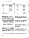
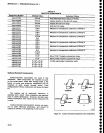
Most
semiconductor..types,
both
separatety
and
in
assembliEs,
are
susceptible
to
damage
to statii
charge,
see
Table
6-1
for
voltage
levels.
WJrecommend
static
sensitive procedures
be implemented
for
att
operations
involving
semiconductor
handling.
Obtalning
Replacement
parts
All
electrical
and
mechanical
parts
are
available
through your
locat
Tektronix
Field
dffic;
oi'r"pr"r"nt"-
tive.
The
Replaceabte
parts
rist
section
contains
infor-
mation
on
how
to order
these
replacement
parts.
Some
components
that
are
heat
sinked
to
the circuit
board
extrusion
or
module
wall,
are
soldered
to
the
board
after
the
board
is
mounted
in
place.
This
is
necessary
to
avoid
cracking
the case
when
the
mounting
lgrew
ls
tightened.
These
components
are
identified
by a
note
on
the
schematic
draw-
ilg.
.Their
part
number
appears
with
chassis
mounted
componenis
in
the
Replaceable
Electrical
parts
list.
Parts
orientation
and
lead
dress
should
be
dupli_
cated
because
some
components
are
oriented
to
reduce
interaction
between
circuits
or
control
circuit
characteristics.
Where
applicable,
an
improved
part
will
b€
substi_
tuted.when
a
replacement
is
ordered.
tf
the change
is
complex, your
local
Field
Office
or
representative
will
contact you
concerning
the change.
After
repair,
the
circuits
may
need
recalibration.
Parts
Repair
and
Return
program
Assemblies
containing
hybrid
circuits
or substrates
in
a semi-sealed
module,
and
complex
assemblies
such
as
ths 1st
LO,
829
MHz
conv€rter,
or
phase
gate
ctetec-
tor,
can
be returned
to
Tektronix
for
repair
under
the
repair
and
return
program.
Tel(ronix
iepair
centers provide
,replacement
or
repair
service
on
maior
assemblies
as
well
as
the
unit.
Return
the
instrument
or
assembly
to
your
local
Field
Office
for
this seMce,
or
contact
your
l6cat
Field
Oftce
for
repair
and exchange
rates.
Firmware
Version
and
Error
Message
Readout
This
feature
provides
readout
of
the
firmware
ver_
sion
when
the
power
on/off
is cycled.
During
the initial
power-up
cycle,
the instrument
firmware
and
iront
panel
firmwar€
versions
are
displayed
on
the
crt
for approxi_
mately
two
seconds.
The
Replaceabte
Electrical
parts
list
section,
under
Memory
board
(A54),
lists
the
ROM
devices
and
their
Tektronix part'
numbers
for
each
firmware
version.
Whenever
an error
occurs
in an
operational
routine,
an
eror
message
on
screen
describes
the
nature
of
the error.
Status messages
or
prompts
(see
Diagnosi-
tics
part
of
this section),
are also
displayed
when
run-
ning
a
diagnostic
test
or calibration proceiure.
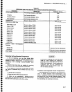
Selected
Components
A few components
that are
selected
to meet
certain
parameters
such
as
temperature
compensation,
or
to
center
the range
of
some
adjustable
component.
The
selected
components
are
identified
as
selectable
on
the
circuit
diagram
and
in
the Replaceable
Electrical
Parts
list.
The
Replaceable
parts
list
description
for
the
component
gives
either
a nominal
vatue.
The
procedure
for
selection
is
explained
in
the adjustment part
of
recalibration procedure.
Table
6-4
lists
these com-
ponents,
their nominal
values, and
the criteria
for
selec_
tion.
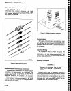
Replacing
EPROM
or ROM
Devtces
Firmware
for
the
microcomputer
is
contained
in
ROM
packs
on
the Memory
and
GplB
boards.
Refer
to
the
Replaceable
Electrical
parts
list (vot.
2)
under these
assemblies
(A54
Memory
and
A56
GplB)
for
the
ver-
sions
and integrated
circuit
part
numbers.
All
integrat€d
circuits
are
soldered
into
sockets on
the
board
to reduce
problems
that occur
due
to
poor
con-
tact
becaus€
of corrosion
or
loose
pins.
Refer
to
replacing
Transistor
and
Integrated
Circuit
for
pro-
cedure.
6-1s