


Theory
of
Operation
-
494A/494Ap
Service,
Vot.
1
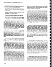
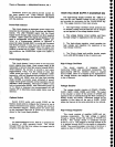
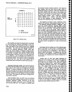
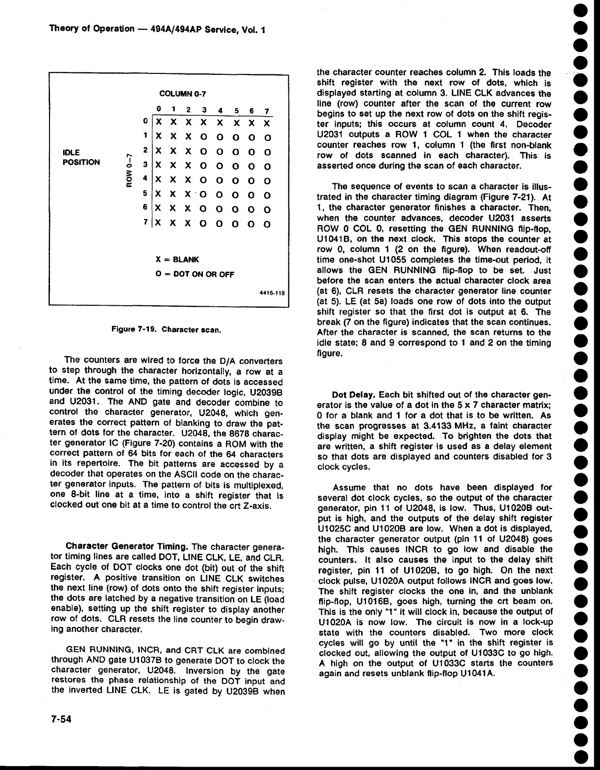
Figure 7-19.
Charaeter
scan.
The counters
are wired
to torce
the D/A
converters
to
step
through
the
character
horizontally,
a
row
at
a
time. At
the
same
time, the
pattern
of
dots
is
accessed
under
the control
of
the
timing
decoder
logic,
U2O39B
and
U2031.
The
AND
gate
and
decoder
combine
to
controf
the character
generator,
U2048,
which
gen-
erates
the
correct
pattern
of
blanking
to
draw th€
pat-
tern of
dots for
thE
character.
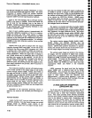
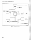
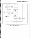
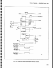
U2048,
the
8679 charac-
ter
generator
lC
(Figure
7-20)
contains
a
ROM with
the
correct
pattern
of
il bits for each
of
the
64 characters
in
its
repertoire.
The
bit
patterns
are
accessed
by
a
decoder
that operates on
the ASCII
code
on
the
charac-
ter
generator
inputs.
The
pattern
of
bits is
multiplexed,
one
8-bit line
at
a time, into
a
shift
register
that is
clocked out
one
bit
at
a
time
to control
the
crt Z-axis.
Character
Generator Timing.
The
character
genera-
tor
timing lines are
called
DOT,
L|NE
CLK,
LE.
and
CLR.
Each
cycle of
DOT ctocks
one
dot
(bio
out
of the
shift
register.
A
positive
transition
on
LINE
CLK
switches
the next line (row)
of
dots onto
the shift
register
inputs;
the
dots
are
latched
by
a
negative
transition
on LE
(load
enable),
setting
up
the
shift
register
to
display another
row
of
dots.
CLR resets
the
line counter
to
begin draw-
ing
another
character.
GEN RUNNING,
INCR,
and
CRT
CLK are combined
through
AND
gate
Ul0378
to
generate
DoT
to
clock
the
character generator,
U2048.
lnversion
by the
gate
restores
the
phase
relationship
of the
DOT
input and
the inverted
L|NE
cLK. LE
is
gated
by
u203gB when
7-54
the character
counter
reaches column 2. This
loads
the
shift
register
with
the
next
row
of
dots, which
is
displayed
starting at column
3.
LINE
CLK
advances
the
line
(row)
counter
after
th€
scan
of
the current
row
begins to
set
up the next row of dots on
the
shift
regis-
ter
inputs; this
occurs
at column count 4.
Decoder
U2031
orrtputs
a ROW 1
COL
1
when
the
character
counter reaches
row 1, column
1
(the
first
non-blank
row of dots scanned in
each
character).
This
is
asserted once during
the
scan of each character.
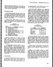
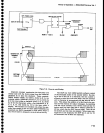
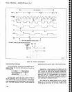
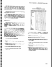
The
sequence of events
to
scan
a character
is illus-
trated in
the
character
timing
diagram
(Figure
7-211.
At
1,
the
character
generator
ftnishes
a character.
Then,
when
the
counter
advances, decoder U2031 asserts
ROW 0
COL
0,
resetting
the GEN RUNNING flip-flop,
U10418,
on
the
n€xt clock.
Thig
stops
th€
count€r
at
row
0,
column
1
(2
on
the
figure). When
readout-ofi
time
one-shot
Ul055
completes
lh€ time-out
period,
it
allows
the GEN RUNNING ftip-flop to b€ set.
Just
before the
scan enters
the
actual character clock
area
(at
6),
CLR
resets
the
character
generator
line
count€r
(at
5).
LE
(at
5a)
loads one
row of dots into
the
output
shift register so
that the
first
dot
is output
at
6. The
break
(7
on
the
figure) indicates
that
the
scan continues.
After
the
character
is
scanned,
the
scan
r€tums
to the
idle state; I
and
9 correspond to
1 and
2 on
the timing
figure.
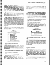
Dot Delay. Each
bit
shifted
out of the character
gen-
erator
is the
value of a
dot
in
ths 5
x
7 character
matrix:
0
for
a blank
and
1 lor
a
dot that
is
to
be
written.
As
ths scan
progresses
at
3.4133
MHz,
a laint character
display
might be
expected.
To
brighten
the dots that
are written,
a shift register
is
used
as a
delay
element
so
that
dots
are
displayed
and counters
disabled
for
3
clock cycles.
Assume
that no dots have b€en displayed
for
several
dot
clock cycles, so
the
output
of
the
character
generator, pin
11
of
U2048, is low.
Thus,
U1020B
out-
put
is
high,
and
the
outputs of
the
delay
shift register
U1025C
and
U10208
are low. When a
dot
is
displayed,
the
character
generator
output
(pin
11 of
U2048)
goes
high. This
causes INCR
to
go
low and
disable the
counters. lt also causes the input to the
delay shift
register,
pin
11 of
U10208, to
go
high.
On the
next
clock
pulse,
U10204
output follows
INCR
and
goes
low.
The shift
register clocks
the
one
in, and
the
unblank
f,ip-flop, U10168,
goes
high, turning
the
crt
beam
on.
This is
the
only
'1"
it will clock in, because th€
output of
U1020A is now
low.
ThE
circuit
is now in a lock-up
state with the
counters
disabled.
Two more clock
cycles
will
go
by until the
"f
in
the shift register
is
clocked
out, allowing
the
output of U1033C to
go
high.
A
high
on the
output of
U1033C
starts
the
counters
again and resets unblank flip-flop
Ul041A.
o
o
o
o
o
o
o
o
o
o
o
o
o
o
o
o
o
o
o
o
o
o
o
o
o
o
o
o
o
o
o
o
o
o
o
o
o
o
o
o
o
o
o
o
IDLE
POStTtON
0
1
2
J3
84
E
5
6
7
COLUMN
0.7
01234567
xxxxxxxx
xxxooooo
xxxooooo
xxxooooo
xxxooooo
x
x
x.o
o
o o
o
xxxooooo
xxxooooo
X:
BLANK
O
:
DOT
ON OR
OFF
44r
Gl18