


o
O
I
o
o
o
o
o
o
a
a
a
o
o
t
a
o
I
a
a
I
o
o
a
a
o
o
a
a
a
t
I
o
a
o
o
O
o
o
o
o
o
o
I
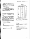
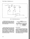
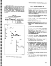
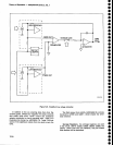
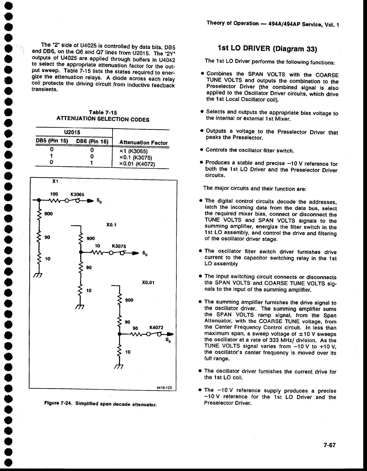
The
2"
side
of
U4025
is
contro[ed
by
data
bits,
DBS
and
DB6,
on
the
e6 and
e7lines
trom
deotS.
The
,,2y,
outputs
of
U4025
are
applied
through
buffers
in u4042
to select
the
appropriate
attenuation
factor
for
the out-
put
sweep.
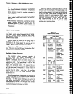
Table
7-1S
lists
the
stat€s
required
to
sner_
gize
the attenuation
relays.
A
diode
across
each
relay
coil
protects
the
ddung
circuit
from
inductive
feedback
transients.
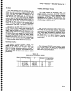
Tabte
7-15
ATTENUATION
SELECTION
CODES
Theory
of
Operation
-
494Al4g4Ap
Servtce,
Vot.
1
1st
LO DRTVER
(Diagram
33)
The
1st
LO Driver performs
the following
functions:
o
combines
the
spAN
voLTs
with
the
coARSE
TUNE
VOLTS
and
outputs
the combination
to
the
Preselector
Driver (the
combined
signal
is also
applied
to
the
Oscillator
Driver
circuits,
which
drive
the 1st Local
Osciilator
coit).
.
Selects
and outputs
the
appropriate
bias voltage
to
the
internal
or
external
1st
Mixer.
o
Outputs
a
voltage
to the
preselector
Driver
that
peaks
the Preselector.
o
Controls
the
oscillator
lilter
switch.
o
Produces
a
stabte
and
precise
-10
V
reference
for
both
the 1st
LO
Driver
and
the
preselector
Driver
circuits.
The
major
circuits
and
their function
are:
o
The
digilal
control
circuits
decode
the
addresses,
latch
the
incoming
data from
th€
data
bus,
select
the
required
mixer
bias,
connect
or
disconnect
the
TUNE
VOLTS
and
SPAN
VOLTS
signats
to
the
summing
amplifier,
energize
the filter switch
in
the
l
st LO
assembly,
and control
the drive
and
filtering
of
the
oscillator
driver stage.
o
The oscillator
filter
switch
driver furnishes
drive
current
to the capacitor
switching
relay
in
the 1st
LO assembly
o
The
input
switching
circuit
connects
or
disconnocts
the
SPAN
voLTS
and
COARSE
TUNE
VOLTS
sig_
nals
to the input
of
the summing
amplifier.
.
The
summing
amplifier
furnishes
the drive signal
to
the
oscillator
driver.
The summing
amptifier
sums
the
SPAN
VOLTS
ramp
signal,
from
the
Span
Attenuator,
with
the coARSE
TUNE voltage,
from
the
Center Frequency
Control circuit.
In less
than
maximum
span,
a sweep
voltage
of *10V
sweeps
the
oscillator
at
a rate
of
333 MHz/
division. As
the
TUNE
VOLTS
signal
varies
from
-10V
to +10V,
the
oscillator's
center
frequency
is moved
over its
full range.
o
The oscillator
driver
furnishes
the current
drive
for
the
1st
LO
coil.
o
The
-1
0 V reference
supply produces
a
precise
-10V
re[erence
for
the 1st
LO Driver and
the
Preselector
Driver.
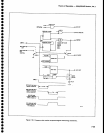
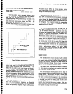
xl
(K3065)
x0.1
(K3075)
x0.01
(K4072)
x1
100
K3065
441&r23
x0.01
Flgwe
7
-2,4.
Simplifi
ed
span
decade
attenuator.
7-67