


Mafnfenance
-
4g4Ll494Ap
Servtce
Vot.
1
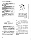
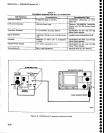
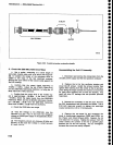
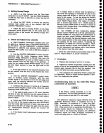
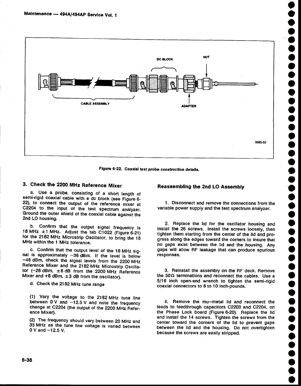
Figure
6-22.
Coaxial
test
probe
construction
detaits.
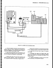
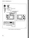
3.
Gheck
the 2200
MHz
Relerence
Mixer
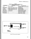
a.
Use a
probe,
consisting
of
a
short
length
of
semi-rigid
coaxial
cabte
with a
dc
block (see
Figure
6_
22),
to connect
the
output
of the
reference
mixer
at
Q2204-to
the input
of
the test
spectrum
analyzer.
Ground
the outer
shield
of
the
coaxial
cable
againsi
the
2nd
LO housing.
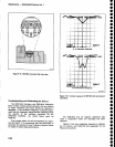
b.
Conftrm
that
the
output
signal
frequency
is
18
MHz *1
MHz.
Adjust
the
tab
C1022
6ilure
O_et1
for
the 2182MHz
Microstrip
Osciilator,
to
Lring
the 1ti
MHz
within
the
1
MHz
tolerance.
c.
Confirm
that
th€
output
level
of
the
1g
MHz
sig_
nal
is
approxirnately
-36
dBm.
lf
the
level
is
below
-46
dBm, check
the signat
levets
from
the
2200
MHz
Reference
Mixer
and
the
2192
MHz
Microstrip
oscilla-
tor
(-28
dBm, *8
dB
from
the
22OO
MHz
Reference
Mixer
and
+8
dBm,
*g
dB from
the oscillator).
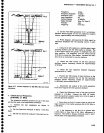
d.
check
the 2192
MHz
tune range
(1)
Vary
the vottage
to the 21g2MHz
tune line
between
0 V
and
-12.5
V
and
note
the fr€quency
change at
c22a4
(the
output
of
the
22oo
MHz
Refei_
ence
Mixer).
(2)
The frequency
should
vary
between
20
MHz and
35
MHz as
the
tune
line
voltage
is
varied
between
0 V and
-12.5
V.
Reassembling
the
2nd LO
Assembly
1. Disconnect
and
remov€
the
connections from
the
variable
power
supply
and the
test
spectrum
analyzer,
2.
Replace
the
lid for
the
oscillator
housing
and
install
the
26 screws.
Install the
screws
loosely,
then
tighten
them starting
from
the
center
of
the lid
and
pro-
gress
along
the
edges
toward the
corners
to
insure
that
no
gaps
exist
between
the
lid
and
the housing, Any
gaps
will allow
RF
leakage
that can
produce
spurious
respons€s.
3. Reinstall
the
assembly
on
the RF
deck.
Remove
the 50O
terminatlons and
reconnect
the
cables.
Use
a
5116 inch
open-end
wrench
to tighten
the
semi-rigid
coaxial connectors
to 8
to
10 lnch-pounds.
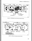
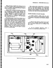
4. Remove
the
mu-metal
lid
and
reconnect the
feads
to
feedthrough
capacitors
C22Og
and
C2204,
on
the Phase Lock
board
(Figure
6-20). Replace the lid
and
install
the 14 screws.
Tighten
the screws
from
the
center
toward
the corners of
the
lid
to
prevent
gaps
between
the lid and
the housing.
Do
not
overtighten
because the screws are
easily stripped.
O
a
o
a
a
o
a
o
o
o
I
a
o
a
a
,
o
a
I
o
o
o
o
o
o
I
o
o
o
t
O
o
o
o
I
o
o
o
o
o
o
O
O
o
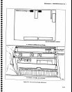
trc BLOC|(
\
_r
CASLE
ASSETBLY
6-38