


7-4
Cisco WAN Manager User’s Guide
Version 10.5, Part Number 78-12945-01 Rev. D0, August 2003
Chapter7 Service Class Template Manager
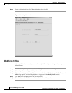
Starting SCT
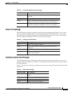
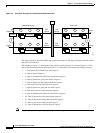
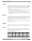
Figure 7-2 Data Flow Through Two Cards Connected Across a Bus
The ingress direction describes traffic that travels toward the bus. The egress direction describes traffic
that travels from the bus.
The numbers in Figure 7-2 correspond to the points at which statistics are collected. Points 1–7 show
data on the incoming path with policing. Points 8–13 show data on the return path without policing.
• 1—Data enters the UNI/NNI port card (ingress).
• 2—Data is queued (ingress).
• 3—Data is scheduled for admission onto the bus (ingress).
• 4—Data is queued for going onto the bus (ingress).
• 5—Data is queued for being taken off the bus (egress).
• 6—Data is processed on the trunk card (egress).
• 7—Data is queued for going out the trunk (egress).
• 8—Data enters the card from the trunk (ingress).
• 9—Data is scheduled for admission onto the bus (ingress).
• 10—Data is queued for going onto the bus (ingress).
• 11—Data is queued for being taken off the bus (egress).
• 12—Data is processed on the port card (egress).
• 13—Data is queued for going out the port (egress).
Note The data flow process might vary depending on the card type.
Ingress
Bus
egress
Bus
ingress
Egress
Egress
Ingress
Policing
12 34
Processing
Bus
13 12 11
Processing
UNI/NNI port card
567
Processing
10 9 8
Processing
Trunk card
Bus
ingress
Bus
egress
47034