B-5
Cisco WAN Manager User’s Guide
Version 10.5, Part Number 78-12945-01 Rev. D0, August 2003
Appendix B Networking
Configuring Network Management
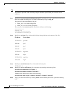
/usr/sbin/route add net 192.0.0.0 172.70.207.6 1
Add this line after the line similar to the following:
/usr/sbin/route add -interface -netmask “240.0.0.0” “224.0.0.0” “$mcastif”
)&
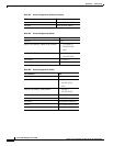
Step 4 Verify your network structures by issuing “netstat -rn” and checking the results against the following
table.
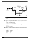
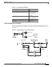
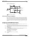
The following tables provide node configuration information about the nodes shown in Figure B-1,
In-Band Management - Basic Hub Attachment Without Router.
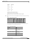
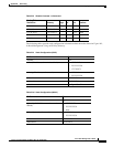
192.0.0.8 bpx4
172.70.207.9 mgx1-lan
192.0.0.9 mgx1
172.70.207.10 mgx2-lan
192.0.0.10 mgx2
IP Address Device Name
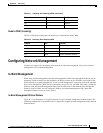
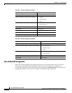
Table B-3 Results of netstat-rn Command
Routing Table Destination Gateway Flags Ref Use Interface
127.0.0.1 127.0.0.1 UH 0 6061 lo0
192.0.0.0 172.70.207.6 UG 0 461 —
172.70.207.0 172.70.207.5 U 3 1311 hme0
224.0.0.0 172.25.70.8 U 3 0 hme0
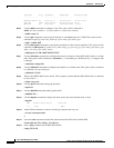
Table B-4 Node Configuration (IGX2)
CLI Command Data
cnfname igx2
cnflan (IP address, subnet mask,
default)
• 172.70.207.6
• 255.255.255.0
• none
cnfnwip (IP address, subnet mask)
• 192.0.0.6
• 255.255.255.0
cnfstatmast 172.70.207.5
cnffwswinit 170.70.207.5
cnfswfunc Configure/Save/Restore


