


Page 134 of
378
ITG Engineering Guidelines
553-3001-202 Standard 1.00 April 2000
bandwidth use of the G.711 codec series, it is recommended that no more than
two ITG cards share the same LAN collision domain in a G.711-only ITG
network.
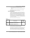
If you use a mixed codec ITG network or use a non-default payload size or
fax settings, then you must use the LAN bandwidth consumption in Table 5
to estimate the amount of LAN bandwidth used by each card. It is
recommended that you do not use the 10Mbit/s collision domain beyond
25-30% at the peak.
If the uplink from the T-LAN hub (either passive or switched) to the router is
10Mbit/s, then the maximum number of ITG cards allowed per hub is equal
to the limit described in the previous paragraph. If the uplink is 100Mbit/s,
then the maximum number of ITG cards allowed on the switched hub is
subject to the limits described in the “Leader Card Real Time Engineering”
section of this document.
You may want to consider implementing LAN resiliency. This is achieved by
provisioning Leader and Follower cards on separate Ethernet hubs (but
served by the same router). In this design the ITG node can provide voice
services when one of the hubs fails.
The ITG node and the T-LAN router should be placed as close to the WAN
backbone as possible, again to minimize the number of router hops, segregate
constant bit-rate Voice over IP traffic from bursty LAN traffic, and simplify
the end-to-end Quality of Service engineering for packet delay, jitter, and
packet loss. If an access router separates the ITG node from the WAN router,
there should be a high-speed link (e.g., Fast Ethernet, FDDI, SONET, OC-3c,
ATM STS-3c) between the access router and the WAN backbone router.
Setting the Quality of Service threshold for fallback routing
The Quality of Service thresholds for fallback routing are configured in the
MAT application. A threshold is configured for the “Receive fall back
threshold” as well as the “Transmit fall back threshold.” The available
thresholds are: “Excellent, Good, Fair, and Poor.”
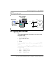
Basic setup of the ITG system
Figure 19 shows an example of a basic recommended ITG system setup, with
separate voice and management networks. This is for illustrative purposes,
and is not necessarily the setup you must use.