


Install and configure ITG ISL Trunk node Page 171 of
378
ITG Trunk 2.0 ISDN Signaling Link (ISL) Description, Installation and Operation
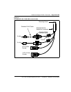
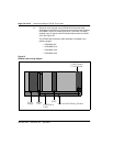
4 Connect the appropriate NTND26 cable assembly to the D-Channel
port connector on the faceplate of the MSDL card and to the inward
side of the 15-pin filter connector installed in the I/O panel of the IPE
Module that contains the DCHIP card.
5 Connect the DCH (P5) connector of the NTCW84KA to the outward
side of the 15-pin I/O panel filter connector.
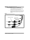
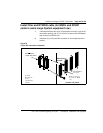
Install filter and NTND26 cable (for MSDL and DCHIP
cards in different Large System equipment rows)
6 Install the bracket for the 15-pin I/O panel filter connector in the J16,
J17, J37 or J38 I/O panel opening of the I/O panel of the Network
Module or Core/Net Module that contains the MSDL card.
7 Install the 15-pin I/O panel filter connector on the inward side of the
bracket.
8 Obtain the correct length of the NTND26 DCHI Interface Cable
Assembly to reach from the D-Channel port connector on the faceplate
of the MSDL card to the outward side of the 15-pin filter connector
installed in the I/O panel of the IPE Module that contains the DCHIP
card.
The NTND26 DCHI Interface Cable Assembly is available in the
following lengths:
• NTND26AA 6 ft.
• NTND26AB 18 ft.
• NTND26AC 35 ft.
• NTND26AD 50 ft.
9 Connect the appropriate NTND26 cable assembly to the D-Channel
port connector on the faceplate of the MSDL card and to the outward
side of the 15-pin filter connector installed in the I/O panel of the IPE
Module that contains the DCHIP card.
10 Use the NTMF04BA Extension Cable to connect the DCH (P5)
connector of the NTCW84KA to the inward side of the 15-pin I/O panel
filter connector.