


Page 218 of
378
Install and configure ITG ISL Trunk node
553-3001-202 Standard 1.00 April 2000
6 Press the reset button on the faceplate to reboot the Leader 0 ITG
Trunk card.
After the reboot is completed, the Leader 0 card will be in a state of
“backup leader”. The faceplate display will show “BLDR.” It cannot yet
be in a state of “active leader”, until you have successfully transmitted
the node properties from MAT to the Leader 0 card.
Transmit the node properties, card properties and
dialing plan to Leader 0
Verify that the ITG Trunk cards are disabled in LD32 in the Meridian 1
before transmitting card properties.
Note: It is necessary to disable ITG Trunk cards whenever transmitting
card properties or new software.
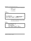
Use the MAT Maintenance Windows, the MAT System Passthru terminal, or
use a Meridian 1 system management terminal directly connected to a TTY
port on the Meridian 1. Use the overlay 32 DISI command to disable the ITG
cards when idle. In the MAT IP Telephony Gateway - ISDN IP Trunk main
window, select
View | Refresh
and verify that the card status is showing
“Disabled”. If the card status is showing “unequipped,” configure the card in
LD14.
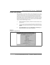
1 From the MAT Navigator window, double-click the ITG ISDN IP
Trunks icon from the Services folder. The IP Telephony Gateway -
ISDN IP Trunk Main window opens.
2 Select the ITG Trunk node for which you want to transmit properties
from the list in the upper part of the window.
3 Select Leader 0 from the list in the lower part of the window
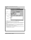
4 In the IP Telephony Gateway - ISDN IP Trunk Main window, select
menu Configuration | Synchronize | Transmit.
5 Leave the radio button default setting of Transmit to selected nodes.
Check the Node Properties, Card Properties and Dialing Plan
check boxes.