


Install and configure ITG ISL Trunk node Page 219 of
378
ITG Trunk 2.0 ISDN Signaling Link (ISL) Description, Installation and Operation
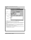
6 Click the Start Transmit button.
Monitor progress in the Transmit Control window. Confirm that the
Node Properties, Card Properties and Dialing Plan are transmitted
successfully to the Leader 0 ITG Trunk card TN. At this point, it is
normal for transmission to Leader 1 and Follower cards to fail.
7 When the transmission is complete, click the Close button.
8 Reboot the Leader 0 ITG card.
Verify installation and configuration
To verify installation and configuration:
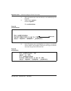
Check card faceplate displays.
After successfully rebooting, the Leader 0 card is now fully configured with
the Node Properties of the node and enters a state of “active leader”. The
faceplate display shows “LDR”.
The Leader 1 card is now autoconfigured as a Leader, reboots automatically,
and enters the state of “backup leader”. The faceplate display shows “BLDR”.
Any follower cards are now auto-configured with their IP addresses and their
display shows “FLR”.
If you have a MAT PC on the local E-LAN subnet, it should now be in
communication with all cards in the ITG Trunk node.
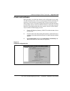
Observe ITG ISL trunk status in MAT
1
From the MAT IP Telephony Gateway - ISDNIP Trunk Main window,
select menu View | Refresh, and verify that the card status is showing
“enabled” or “disabled” (depending on the card status in the
Meridian 1). If any cards show “not responding”, verify:
a the management interface cable connection to the E-LAN
b the voice interface cable connection to the T-LAN
c the management MAC addresses that were entered previously on
the “Configuration” tab of the Node Properties, while adding the
ITG node on MAT.