


Page 360 of
378
Appendix D: Configure a Netgear RM356 modem router for remote access
553-3001-202 Standard 1.00 April 2000
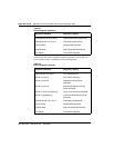
• IP Packet Filtering
• Idle time-out disconnect for dial-in PPP connection.
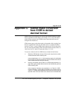
Install the RM356 modem router
1 Place the modem router at a conveniently visible and physically secure
location near an AC power outlet, an analog telephone line, and
10BaseT Ethernet cables. Up to four hosts or hubs can be connected
to the integrated 10BaseT hub in the rear of the RM356 modem router.
Use shielded Cat5 10BaseT Ethernet cables to connect the modem
router to the Management interface of up to four ITG cards. Other
IP-enabled Nortel Networks products on the E-LAN may be connected
to the RM356 modem router, including the Meridian 1 PBX, a local
MAT PC, Symposium Call Center Server, and Call Pilot.
Note:
The up-link connection to an additional E-LAN hub or optional
C-LAN gateway requires either a cross-over 10BaseT Ethernet cable,
or a special up-link port on the 10BaseT hub to which the RM356 is
connected.
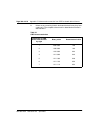
2 When the modem router is connected to the AC power source, the
power LED is lit. After several seconds, the test LED flashes slowly
four times, then stays off. For each of the four 10BaseT ports on the
integrated hub there is a link/data LED that is lit steadily to indicate a
good received link if there is a cable connection to a host or hub that is
powered up, or flashing to indicate data received on the LAN.
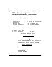
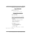
3 Connect the RJ45 plug end of the local manager cable to the RS232
Manager port RJ45 jack on the rear of the modem router. Connect the
other end of the cable to an RS232 terminal or PC COM port
configured for the following communication parameters: 9600 bps, 8,
none, and 1. The local maintenance cable connects directly to data
terminal equipment (DTE).
4 The analog telephone line should be a C.O. line or a PBX extension
with a Direct Inward Dialing(DID) number if that is in compliance with
the customer's network security policy.