


Page 194 of
378
Install and configure ITG ISL Trunk node
553-3001-202 Standard 1.00 April 2000
If you select the single subnet option, the E-LAN is used for the voice and
management network, and all voice and management data goes through the
10BaseT management Ethernet interface (lnIsa0) on the motherboard of the
ITG Trunk card.
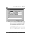
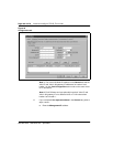
Configure Network Connections
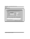
1 Decide subnet settings:
a If you will be using
separate subnets
for the voice (T-LAN) and
management (E-LAN) networks, accept the default setting Use
separate subnets for voice and management check box.
b If you will be using the
same subnet
for the voice and
management network (E-LAN), uncheck the Use separate
subnets for voice and management check box. The window
changes.
2 If you accepted the default setting Use separate subnets, perform
steps a-d.
a Enter the Voice LAN Node IP
b Enter the Management LAN gateway IP
c Enter the Management LAN subnet mask
d Enter the Voice LAN subnet mask fields
The Voice LAN Node IP address on the General tab and the Voice IP
and Voice LAN gateway IP addresses for Leader 0 and Leader 1 on
the Card Configuration tab must be on the same subnet.
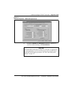
3 If you unchecked Use separate subnets, perform steps a-c:
a Enter the Management LAN Node IP
b Enter the Management LAN gateway IP. The Management
gateway (router) also functions as the voice gateway (router).
c Enter the Management LAN subnet mask
The Management LAN Node IP and Management gateway IP
addresses on the General tab and the Management IP for Leader 0,
Leader 1 and all Follower cards on the Card Configuration tab must
be on the same subnet.
Note:
Do not press OK or Apply until you have completed the
Configuration tab.