


Page 158 of
378
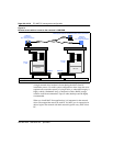
Install and configure ITG ISL Trunk node
553-3001-202 Standard 1.00 April 2000
Install and cable ITG trunk cards
Card installation procedure
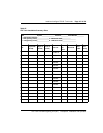
When unpacking the hardware, use ESD precautions while handling the
cards. As each card is placed in the Meridian 1 system, record the TN,
management MAC address and the card density on the installation summary
sheet. The management MAC address is labeled on the ITG Trunk card
faceplate as the motherboard Ethernet address.
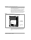
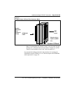
Each ITG card requires two slots in a Meridian 1 IPE shelf. Only the left slot
of the card requires connection to the Meridian 1 IPE backplane and I/O
panel.
At least one DCHIP card must be installed in an ITG ISL Trunk node. You
must install the D-Channel (DCH) PC Card and the associated NTCW84EA
DCHIP PC Card Pigtail cable on to the DCHIP card.
You can install a maximum of eight ITG cards in an IPE shelf. The ITG card
can occupy any two adjacent slots in an IPE shelf, with the left slot of the card
plugging into slots 0 to 6 and 8 to 15. You cannot plug in the left slot of an
ITG card in slot 7, because the XPEC card is situated in-between slots 7 and 8.
To allow a module to hold the maximum number of ITG cards, install each
card with the left slot of the card inserted in an even-numbered slot.
If the maximum card density for each module is not required, the left slot of
the ITG card can be inserted in an odd-numbered slot.