


Install and configure ITG ISL Trunk node Page 195 of
378
ITG Trunk 2.0 ISDN Signaling Link (ISL) Description, Installation and Operation
Configure card properties
These procedures explain how to configure the ITG ISL trunk card roles, IP
addresses, TN, card density and D-Channel settings. Each ITG ISL Trunk
node requires a Leader 0 card and one DCHIP card (which can be Leader 0),
and can have a Leader 1 card, one or more Follower cards, and additional
DCHIP cards (which can be Leader 1 or Follower cards). Either Leader 0 or
Leader 1 can have the Active Leader status. On system power-up, Leader 0
normally functions as the Active Leader and Leader 1 as the Backup Leader.
At other times, the Leader card functions can reverse with Leader 1 working
as the Active Leader and Leader 0 working as the Backup Leader. To add an
ITG card to the node, perform the following steps:
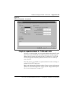
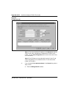
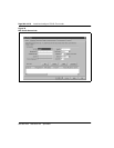
1 From the General tab, click the Configuration tab. If you selected the
single subnet option in the General tab, the Voice IP and Voice LAN
gateway IP fields will be greyed-out.
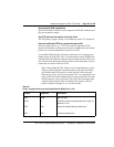
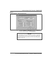
2 Select the Card role from the drop-down list box:
When you add the first card, select the card role Leader 0. When you
add the second card, select the card type Leader 1. When you add
additional cards, select the card type Follower. You configure the
DCHIP and D-Channel information.
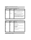
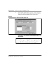
3 If you checked Use separate subnets in the General tab, perform
steps a-d.
a Enter the Management IP address.
b Enter the Management MAC address. It is the motherboard
Ethernet address. You can find it on the faceplate label of the card
you are currently configuring. It is also identified as lnIsa0 on the
card startup messages and by the ifShow command in the ITG
shell.
c Enter Voice IP address (see Notes 1 and 2).
d Enter Voice LAN gateway IP address (see Notes 1 and 2).