


Description Page 41 of
378
ITG Trunk 2.0 ISDN Signaling Link (ISL) Description, Installation and Operation
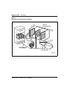
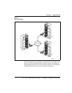
Reset switch
A reset switch on the faceplate allows an operator to manually reset the card
without having to cycle power to the card. This switch is normally used
following a software upgrade to the card or, alternatively, to clear a fault
condition.
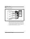
PC Card socket
There are two PC Card sockets. The faceplate socket accepts either a Type I,
II, or Type III PC Card and is designated ATA device A:. The internal socket
is reserved for the NTWE07AA C7LIU DCH PC Card on the DCHIP.
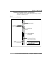
Maintenance displa
y
This is a four character, LED-based dot matrix display. It shows the card boot
sequence and is labeled with the card role as follows:
• LDR = Active Leader
• BLDR = Backup Leader
• FLR = Follower
RS-232 maintenance port
The ITG ISL Trunk card has a DIN-8 serial maintenance port connection on
the faceplate and an alternative connection to the same serial port on the I/O
backplane. Do not connect two maintenance terminals to both the faceplate
and I/O panel serial maintenance port connections at the same time.
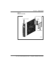
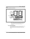
Voice Ethernet port (T-LAN)
The faceplate Ethernet connector is a 9-pin, sub-miniature D-type connector.
The voice Ethernet port on the daughterboard is identified as “lnPci1” in the
ITG shell.
WARNING
Do not connect a T-LAN cable to the Faceplate 9-pin Voice port
connector (NWK). You must connect the T-LAN cable to the I/O
cable.