


Install and configure ITG ISL Trunk node Page 159 of
378
ITG Trunk 2.0 ISDN Signaling Link (ISL) Description, Installation and Operation
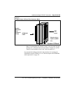
Note 1: The ITG Trunk card requires 24 pair tip and ring I/O cabling.
NT8D37AA IPE modules have 24 pair tip and ring I/O cabling for card
slots 0, 4, 8, and 12 only. You can insert the left slot of the ITG Trunk
card in NT8D37AA slots 0, 4, 8 or 12 only. NT8D37BA or later IPE
modules have no such restriction.
Note 2: When multiple ITG cards are installed, distribute them between
available IPE shelves. This prevents total loss of IP trunking, in the case
of localized shelf failure.
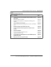
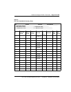
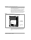
1 Identify the IPE card slots selected for the ITG card(s). Use the
recorded information from the ITG Trunk Installation Summary Sheet
(Figure 27 on page 157).
2 Remove any existing I/O panel cables associated with any card
previously installed in the selected card slot.
CAUTION
Wear an electrostatic discharge strap when handling ITG cards. As an
additional safety measure, handle all cards by the edges and, when
possible, with the loosened packaging material still around the
component.
CAUTION
Never install an ITG card in an IPE shelf that has been wired for a
Central Office Trunk (COT) card. Before you insert the card into the slot,
disconnect the cable connecting this card to the Main Distribution Frame
(MDF). COT cards can receive ringing voltage, which, when applied to
an ITG card, can damage the card.
CAUTION
Do not overtighten screws. They can break.