


Install and configure ITG ISL Trunk node Page 191 of
378
ITG Trunk 2.0 ISDN Signaling Link (ISL) Description, Installation and Operation
Disable the ITG Trunk cards
In order to transmit the card properties from MAT to the ITG Trunk cards, the
ITG Trunks must be in the disabled state.
To disable an ITG trunk card, use the following command in LD32 or in MAT
Maintenance Windows: DISI l s c u.
Wait for NPR0011 to be output. Requested pack is no longer busy and has
been disabled. This indicates that the DISI command has been completed.
The status of the ITG trunk card in MAT is updated to disabled.
The cards must be enabled later after the card properties and optionally, the
new card software, has been transmitted from MAT to the ITG Trunk cards.
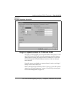
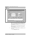
Configure ITG Trunk data on MAT
Before you can use this procedure, you must get all the IP addresses for the
new ITG Trunk node from your network administrator and add them to your
installation summary sheet. Use the installation summary sheet to facilitate
data entry into MAT. You will also need the node IP addresses of any existing
ITG Trunk nodes in the network.
Note: Refer the network administrator to the Engineering Guidelines
section for information on ITG Trunk IP address requirements.
An ITG node is a collection of ITG cards in an Meridian 1 system for a
selected customer.
Each node in the ITG network has a property sheet that configures the options
that apply to the node’s cards.
MAT stores Node Properties data. This data generates the bootptab file. You
transmit the data to the Active Leader.
Note: The bootptab file is a configuration file that downloads to the
Active Leader card. It contains the list of cards and related IP and MAC
addresses for the node. “Bootptab” is short for “bootp table”. When
transmitted to the ITG Active Leader card, it is renamed “bootp.1”.