


The Graphical Waveform Editor
3-66 AWG710&AWG710B Arbitrary Waveform Generator User Manual
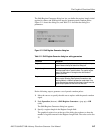
Shift Register Generator...
The Shift Register Generator... command specifies a shift register to generate
pseudo–random pulses with the value of 1 or 0 that replace the waveform data in
the edit area. The pseudo–random shift generator consists of a user–definable
register size (1 to 32 bits) and a user–specified number of feedback taps that do an
XOR operation between a specified register bit and the register output.
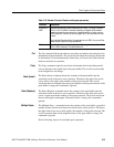
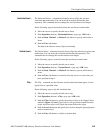
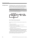
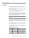
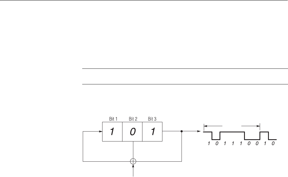
Figure 3-10 shows an example of the pattern generated for a 3–bit register with an
initial value of 101 and a single tap on register bit 2.
Figure 3-10: Register value and tap setting example
The following steps describe how the instrument generates the output waveform
values.
1. Output 1 of the rightmost bit.
2. Take XOR of the output value 1 and the Bit 2 value 0 (result is 1).
3. Shift the bit values one column to the right.
4. Assign the value 1 to Bit 1, which is the XOR value from Step 2. The new array
of the register values is 110.
5. Repeat steps 1 to 4, with 110 as the register value.
6. Repeating output of the rightmost bit of the register and the subsequent shift of
the register value results in the output values as shown in Figure 3-10. In this
example, the shift register output pattern starts to repeat after seven cycles.
The data generated by the shift register is called an M Series. If n is defined as the
number of shift register bits, then the output pattern from the shift register
generator (M Series length) will begin to repeat after 2
n
- 1 cycles.
NOTE. XOR (exclusive OR) is a boolean logic operation that outputs one if two
input values are different and outputs 0 otherwise.
1 CycleOutput
Ta p