The Pattern Editor
3-86 AWG710&AWG710B Arbitrary Waveform Generator User Manual
Starting the Pattern Editor
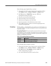
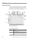
To start the Pattern Editor, push EDIT (front)! Edit (bottom)!New Pattern
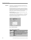
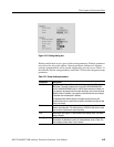
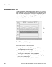
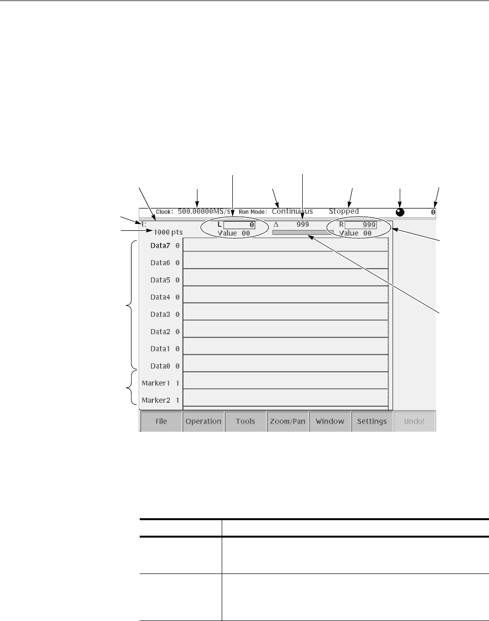
(side). Figure 3-17 shows the Pattern Editor screen elements. All Pattern editor
screen elements are the same as for the Waveform Editor (page 3-56) except for
those listed in Table 3-23. All Pattern Editor bottom menu items are the same as for
the Waveform editor (page 3-57) except for those listed in Table 3-24.
Figure 3-17: Pattern editor initial screen
Marker display
Pattern display
Data record length
Window number
Pattern
file name
Clock frequency
Left cursor position
field and data value
Run mode
Cursor-to-cursor
distance (edit area)
Status
display area
Knob Icon
Active cursor
position
Right cursor
position
field and
data value
Edit area
position bar
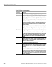
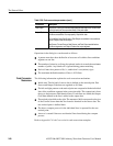
Table 3-23: Pattern editor screen elements
Element Description
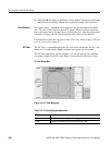
Pattern display The pattern display is a graphical representation of the pattern data values.
There are a total of 8 data bits (Data0 through Data7) and two marker
signals. Data values are 1 or 0.
Pattern file name The pattern file name is a file name to which the waveform data is written.
The instrument appends the .PAT file extension to all pattern files. If this is
a new pattern, you are prompted to enter a file name before exiting the
editor.


