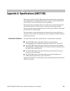
Appendix A: Specifications (AWG710B)
AWG710&AWG710B Arbitrary Waveform Generator User Manual A-5
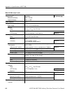
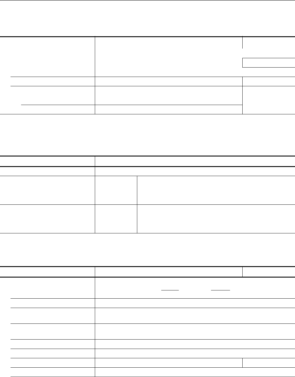
Range 500 mV
p–p
to 1 V
p–p
, into a 50 Ω load
nDC Accuracy ±(2 % of Amplitude + 2 mV) Page B-27
Resolution 1 mV
n DC offset accuracy 0 V ± 10 mV, (500 mV amplitude, waveform data: 0) Page B-27
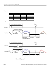
n Pulse response (Waveform data: -1 and 1, at 1 V
p–p
) Page B-29
Rise time (10 % to 90 %) ≤ 175 ps (calculated value ≥ 2 GHz)
Fall time (10 % to 90 %) ≤ 175 ps (calculated value ≥ 2 GHz)
3
The characteristics are specified at the end of the SMA cable (174–1427–00) except for DC accuracy.
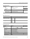
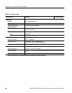
Table A-6: Main output (cont.)
Characteristics
3
Description PV reference page
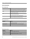
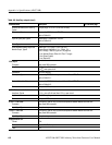
Table A-7: Filter (except option 02)
Characteristics Description
Type Bessel low pass filter, 200 MHz,100 MHz, 50 MHz, and 20 MHz
Rise time (10 % to 90 %), Typical 20 MHz
50 MHz
100 MHz
200 MHz
17 ns
7 ns
3.7 ns
2 ns
Group delay, Typical 20 MHz
50 MHz
100 MHz
200 MHz
18 ns
8 ns
4.7 ns
3 ns
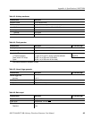
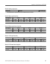
Table A-8: Auxiliary outputs
Characteristics Description PV reference page
Marker
4
Number of markers 2 (Complementary). Marker1, Marker1, Marker2, and Marker2
Connector Front panel SMA connectors
High Level (VoH)
Range
-1.00 V to +2.45 V, into a 50 Ω load
Refer to Figure A-8 on page A-16
Low Level (VoL)
Range
-2.00 V to +2.40 V, into a 50 Ω load
Refer to Figure A-8 on page A-16
Amplitude (VoH - VoL) Range 0.05 V
p–p
, to 1.25 V
p–p
into a 50 Ω load
Resolution 50 mV
n DC Accuracy ±0.1 V ±5 % of setting, into a 50 Ω load Page B-50
Maximum Output Current ±80 mA


