Appendix B: Performance Verification (AWG710B)
B-36 AWG710&AWG710B Arbitrary Waveform Generator User Manual
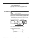
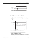
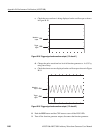
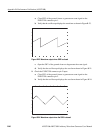
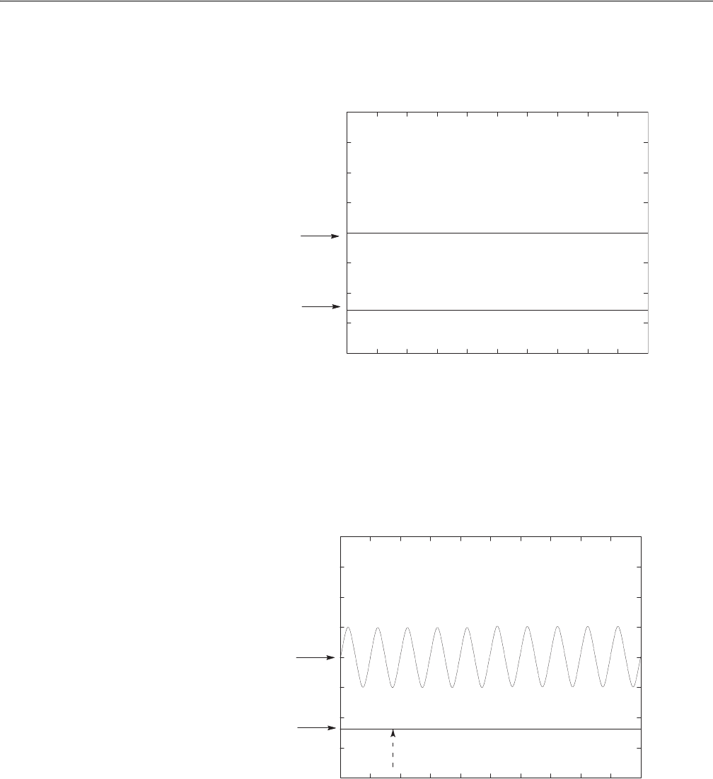
c. Check that no waveform is being displayed on the oscilloscope as shown
in Figure B-18.
Figure B-18: Trigger signal and waveform output (-5 V check 1)
d. Change the pulse waveform low level of function generator to –4.65 V by
using cursor keys.
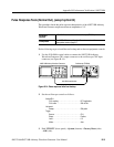
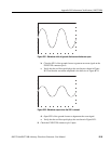
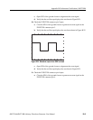
e. Check that sine waves are displayed on the oscilloscope as shown in Figure
B-19.
Figure B-19: Trigger signal and waveform output (-5 V check 2)
8. Push the RUN button and the CH1 button to turn off the RUN LED.
9. Turn off the function generator output, disconnect the function generator.
Waveform
output
Trigger
signal
CH2
CH1
Waveform
output
Trigger
signal
CH2
CH1


