Appendix B: Performance Verification (AWG710)
B-62 AWG710&AWG710B Arbitrary Waveform Generator User Manual
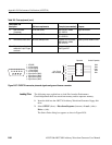
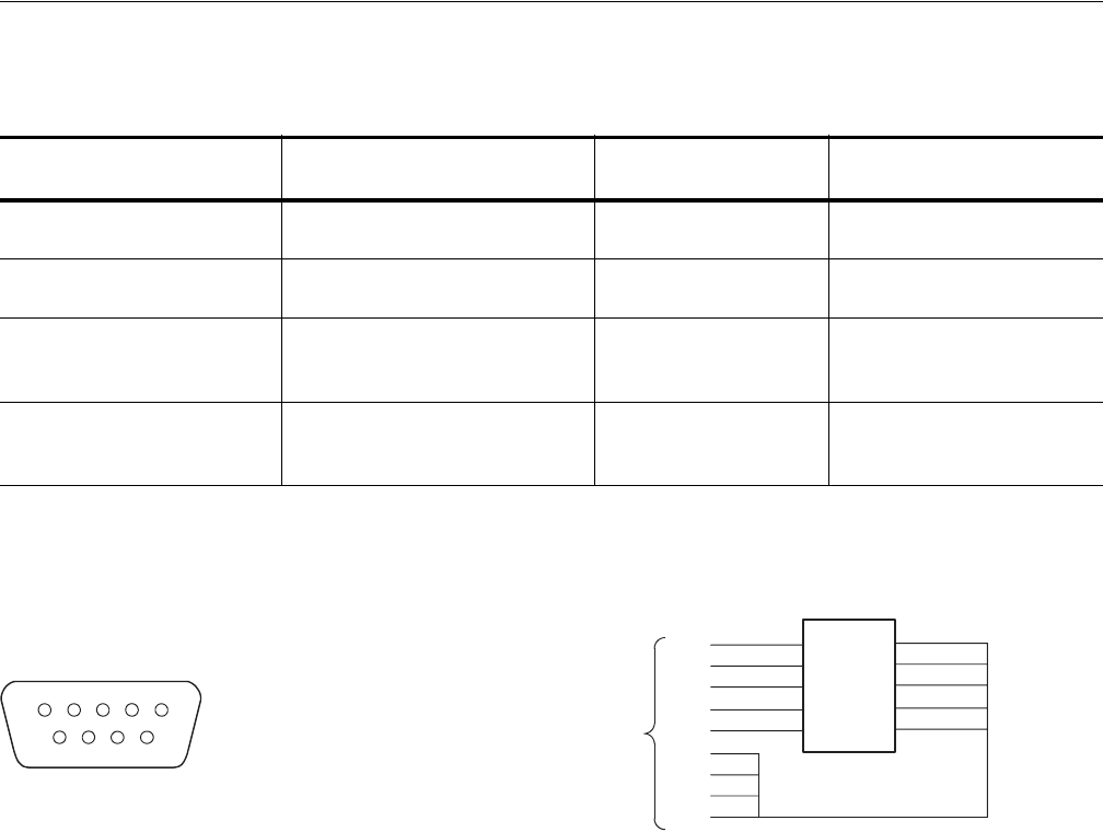
Figure B-37: EVENT IN connector pins and signals and ground closure connector
Loading Files
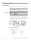
The following steps explain how to load files from the Performance
Check/Adjustment disk into waveform memory and/or sequence memory.
1. Insert the disk into the AWG710 Arbitrary Waveform Generator floppy disk
drive.
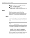
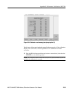
2. Select SETUP (front)!Waveform/Sequence (bottom)!Load... (side)!
Drive... (side).
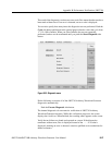
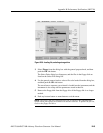
The Select Drive dialog box appears as show in Figure B-38.
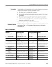
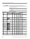
12. SMA Terminator
(2 required)
50 Ω, SMA (male) Tektronix part number
015–1022–01
Signal termination
13. Precision Terminator 50 Ω, 0.1 %, BNC Tektronix part number
011–0129–00
Signal termination
14. Performance check disks Must use example listed Supplied with the product,
Tektronix part number
062–A273–00
Used to provide waveform files.
15. Ground closure (loopback
cable) with 9–pin, D–type
connector
Custom,
See Figure B-37.
Used for event mode test.
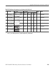
Table B-5: Test equipment (cont.)
Item number and
description Minimum requirements Example (recommended) Purpose
1STROBE
2 3 (Event Signal)
3 2 (Event Signal)
4 1 (Event Signal)
5 0 (Event Signal)
6 Signal Ground (GND)
8 Signal Ground (GND)
7 Signal Ground (GND)
9 Signal Ground (GND)
12345
9876
1
2
3
4
5
9
8
7
6
1
2
3
4
5
9
8
7
6
10
Switch ID symbols
Dip switch
SW5
SW4
SW3
SW2
SW1
9-pin, D-type,
male connector


