FG Mode
3-238 AWG710&AWG710B Arbitrary Waveform Generator User Manual
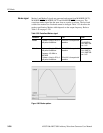
Marker signal
Marker1 and Marker2 signals are generated and output from MARKER OUT1,
MARKER OUT1
, MARKER OUT2 and MARKER OUT2 connectors. The
waveform marker signal has the same form as a pulse waveform. The level and
width of the markers are fixed and cannot be changed. Table 3-55 describes the
marker specification. Marker width depends on the output frequency. Refer to
Table 3-56 on page 3-239.
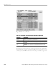
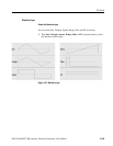
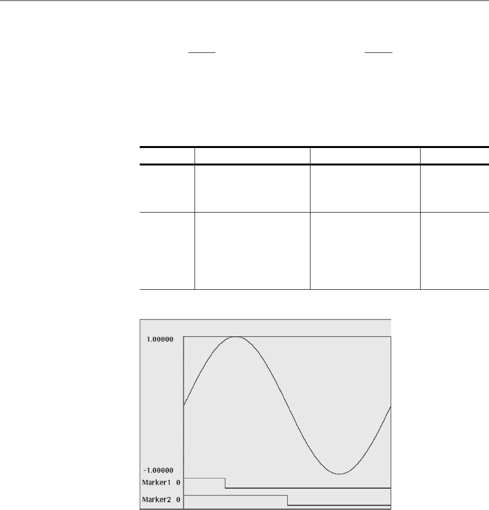
Figure 3-80: Marker pattern
Table 3-55: Predefined Marker signal
Waveform Hi Low Level
Marker1 0 (phase = 0 deg.) to 20 % of
one period of waveform
20 to 100 % of one period of
waveform
Hi :
2.0 V:AWG710
1.0 V :AWG710B
Low : 0.0V
Marker2 0 (phase = 0 deg.) to 50 % of
one period of waveform
Frequency: 100.1MHz to
160.0MHz
0 (phase = 0 deg.) to 52 % of
one period of waveform
50 to 100 % of one period of
waveform
52 to 100 % of one period of
waveform
Hi :
2.0 V :AWG710
1.0 V :AWG710B
Low : 0.0V


