


Appendix A: Specifications (AWG710B)
A-6 AWG710&AWG710B Arbitrary Waveform Generator User Manual
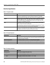
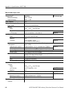
Rise and fall times (20 % to 80 %),
Ty p i c a l
<130 ps (High: 1.0 V, Lo: 0 V, into a 50 Ω load)
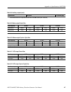
Period jitter, Typical Measured by TDS6604 with TDSJIT3.
Refer to Table A-9.
Cycle to Cycle jitter, Typical Measured by TDS6604 with TDSJIT3.
Refer to Table A-10.
Skew, Typical <20 ps
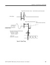
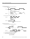
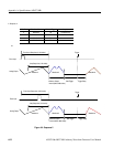
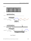
Delay between Analog Output and
Marker Output, Typical
Maker level: 1 V
p-p
(High: +1.0 V, Low: 0 V),
Analog Output Amplitude: 1 V
p-p
, Offset: 0 V,
Filter: Through, Refer to Figure A-1 on page A-9
2.4 ns (Normal Output, Offset: 0 V, Filter: Through)
-1.0 ns (Direct Output)
2.0 ns (Option 02)
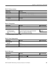
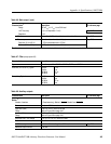
VCO output
Connector Rear panel SMA connector
Amplitude 0.4V
p-p
into a 50 Ω load
0.8 V
p-p
max. open circuit
Impedance 50 Ω, AC coupling
Period jitter, Typical Measured by TDS6604 with options 1M and HD and TDSJIT1.
Refer to Table A-11.
Cycle to Cycle jitter, Typical Measured by TDS6604 with options 1M and HD and TDSJIT1.
Refer to Table A-12.
Connector Rear panel SMA connector
10 MHz Reference clock out
Amplitude, Typical 1.2 V
p–p
, into a 50 Ω load, Max 2.5 V
p–p
, open circuit
Impedance 50 Ω, AC coupling
Connector Rear panel BNC connector
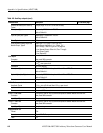
C Out 1, C Out 2 out This signal is used for only Synchronous operation between Master and Slave unit.
Connector Rear panel SMA connector
Input Signal Type Complementary
T Out 1, T Out 2 out This signal is used for only Synchronous operation between Master and Slave unit.
Connector Rear panel SMA connector
Input Signal Type Complementary
Display Monitor out
Format VGA
Connector 15 pin, D-SUB, Rear panel
Level ECL
Table A-8: Auxiliary outputs (cont.)
Characteristics Description PV reference page