Appendix A: Specifications (AWG710)
A-32 AWG710&AWG710B Arbitrary Waveform Generator User Manual
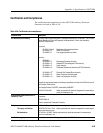
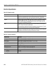
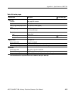
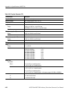
10 MHz Reference clock out
Amplitude, Typical ≥ 1.2 V
p–p
, into a 50 Ω load, Max 2.5 V
p–p
, open circuit
Impedance 50 Ω, AC coupling
Connector Rear panel BNC connector
4
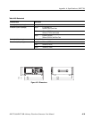
The characteristics are specified at the end of the SMA cable (012–1565–00).
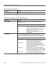
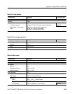
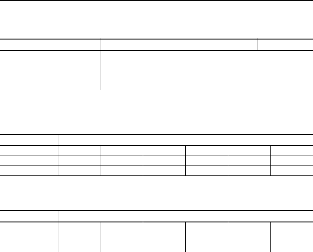
Table A-36: Auxiliary outputs
Characteristics Description PV reference page
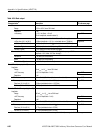
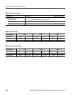
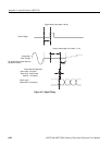
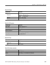
Table A-37: Period Jitter
Clock frequency 4 GS/s 2 GS/s 1 GS/s
Measurement StdDev Pk-Pk StdDev Pk-Pk StdDev Pk-Pk
Marker output 1.6 ps 11.6 ps 1.9 ps 13.4 ps 2.5 ps 15.1 ps
1/4 Clock output 2.6 ps 20.2 ps 2.4 ps 27.5 ps 1.9 ps 14.0 ps
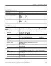
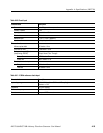
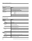
Table A-38: Cycle to Cycle Jitter
Clock frequency 4 GS/s 2 GS/s 1 GS/s
Measurement StdDev Pk-Pk StdDev Pk-Pk StdDev Pk-Pk
Marker output 3.1 ps 21.4 ps 3.2 ps 26.1 ps 3.1 ps 21.9 ps
1/4 Clock output 4.8 ps 44.5 ps 3.7 ps 33.3 ps 3.1 ps 28.7 ps


