


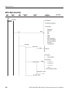
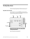
The Setup Menu Screen
3-34 AWG710&AWG710B Arbitrary Waveform Generator User Manual
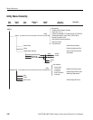
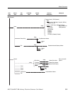
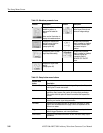
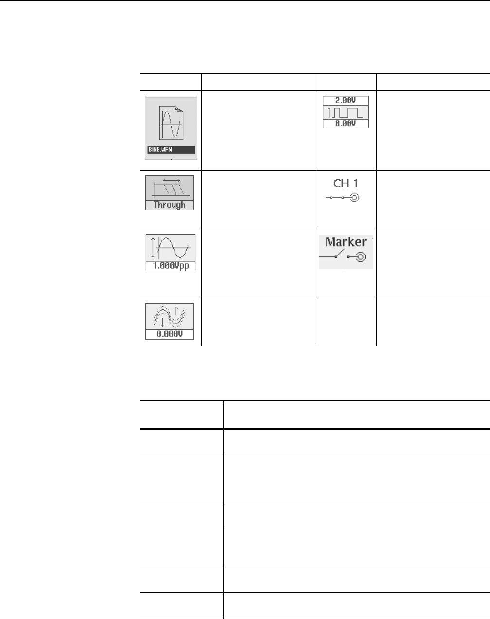
Table 3-2: Waveform parameter icons
Element Description Element Description
Displays the file name of the
waveform, pattern, or
sequence file loaded for
output.
Note: use the View button to
display the loaded waveform.
Displays the digital output and
marker signal minimum and
maximum voltage settings.
Displays the lowpass filter
setting through which the
waveform is passed.
(except option 02)
Indicates that the channel
output is enabled or disabled.
If the switch is shown open,
that channel output is
disabled.
Displays the peak–to–peak
signal amplitude setting.
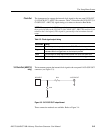
Indicates that the marker
output is enabled or disabled.
All Marker outputs are
controled by the ALL
MARKER OUT ON/OFF
button.
Displays the signal offset
setting.
(except option 02)
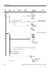
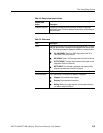
Table 3-3: Setup bottom menu buttons
Bottom menu
button Description
Waveform/Sequence Displays the side menu for loading, viewing, editing waveform files, and
entering the FG mode main screen.
Vertical Displays the Vertical side menu for setting waveform peak–to–peak
amplitude, offset, lowpass filter, marker, and other output parameters.
The product which has option 02 doesn’t have offset and lowpass filter
function.
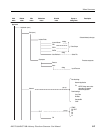
Horizontal Displays the Horizontal side menu for setting the clock source, clock
frequency, and marker signal delay parameters.
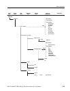
Run Mode Displays the Run Mode side menu for setting the instrument run mode.
Refer to the Run Modes section on page 3-44 for an explanation of the
different run modes.
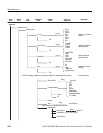
Trigger Displays the Trigger side menu for setting trigger source, slope, level,
external trigger impedance, and interval parameters.
Save/Restore Displays the Save/Restore side menu to save and restore setup output
parameters.