


The Graphical Waveform Editor
3-56 AWG710&AWG710B Arbitrary Waveform Generator User Manual
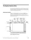
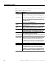
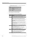
Table 3-8 provides a description of the Waveform editor screen elements.
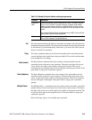
Table 3-8: Waveform editor screen elements
Element Description
Active cursor position The position of the active cursor in the data record relative to the start of
the data record. Position is stated as point location or time depending on
the horizontal unit set with the Settings menu.
Clock frequency The clock frequency (sample rate) used to calculate the point–to–point time
interval between each data point. This value is set in the Settings menu.
Note that this value is not the output waveform frequency. Output frequency
is calculated as follows:
Freq
out
= Freq
clk
/ points per waveform cycle
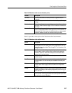
Cursor–to–cursor
distance
The number of data points or time between the left and right cursors.
Distance is stated as points or time depending on the horizontal unit set
with the Settings menu.
Waveform record
length
The record length of the entire waveform file, in points. Record length is
always shown as points regardless of the horizontal unit set with the
Settings menu. The default value is 1000 points.
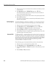
Edit area position bar The edit area position bar is relative to the position of the displayed edit
area in the entire record length. This helps you determine where you are in
a waveform record when you do zoom operations on the display area.
Window number The edit window number is from one to three. The maximum number of
editor windows you can open at one time is three.
Knob icon The knob icon is displayed when you can use the general purpose knob to
change a highlighted field.
Left cursor position
field and data value
The position of the left cursor and the data value at that position. Cursor
position 0 is the start of the data record. Position is stated as point location
or time depending on the horizontal unit set with the Settings menu.
You use the TOGGLE front–panel button to select between the left or right
cursor. When the left cursor is active, you can use the general purpose
knob or the Keypad buttons to change the cursor position.
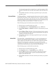
Marker display The marker display is a graphical representation of the marker data values.
Right cursor position
field and data value
The position of the right cursor and the data value at that position. Cursor
position 0 is the start of the data record. Position is stated as point location
or time depending on the horizontal unit set with the Settings menu.
You use the TOGGLE front–panel button to select between the left or right
cursor. When the right cursor is active, you can use the general purpose
knob or the Keypad buttons to change the cursor position.