


AWG710&AWG710B Arbitrary Waveform Generator User Manual 3-85
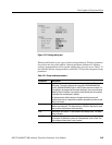
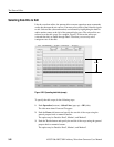
The Pattern Editor
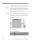
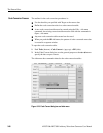
The Pattern Editor lets you create and edit data to output the analog signal. Graphic
and tabular are the two display modes. The graphic mode displays the waveform
graphically, while the tabular mode displays the tubular mode numerically in
tabular form.
The instrument will interpret the data bit values and send the resulting signal to the
CH 1 or CH1
output.
About Waveform and Pattern Files
You can load both the waveform and pattern files to output a waveform to CH1 and
CH1
. When you load a waveform file, the instrument converts the file to an 8–bit
digital pattern and stores the pattern into the waveform memory. At the same time,
the instrument stores the data in the pattern file into the waveform memory without
any conversion.
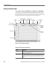
The waveform file format is composed of 4–bytes for each data point and 1–byte
for markers. The pattern file format is composed of 2–bytes including data and
markers.
When you transfer the data, select pattern file to shorten the transfer time if you are
not going to perform other operations on the data. The number of bytes in the
pattern file is always less than that of the waveform file even though they are the
same data length.
However, when you use waveform data to generate another waveform by
mathematical operations, such as multiplying, dividing, or adding, you must keep
the waveform data as a waveform file. The waveform file format exists for keeping
the data precision in mathematical operations.
For more details about file format, refer to the Data Transfer section in the
AWG710&AWG710B Arbitrary Waveform Generator Programmer Manual.