


Operating Basics
AWG710&AWG710B Arbitrary Waveform Generator User Manual 2-39
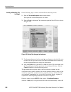
Outputting a Waveform
To output a loaded waveform, push the CH 1 OUT and/or CH 1 OUT and/or ALL
MARKER OUTPUT ON/OFF front–panel button(s), then the RUN front–panel
button. The LEDs near each button light up to indicate they are enabled. The
instrument outputs the waveform depending on the Run mode. You can turn either
or both channel outputs and marker outputs on or off while the instrument is
running by pushing the CH 1 OUT or CH 1
OUT or ALL MARKER OUTPUT
Horizontal Clock
Clock Ref
Clock Src
(AWG710B only)
Sets the clock sample rate from 50 kS/s to 4.0 GS/s.
Sets the reference clock source to either Internal or External.
A valid external clock signal is 10 MHz ±0.1 MHz with a
voltage level of 0.2 to 3.0 V
p–p
.
Sets the clock source to either Internal or External. A valid
external clock signal is 125 MHz to 4.2 GHz with a voltage
level of 0.4 to 2.0 V
p–p
.
Run Mode Continuous
Triggered
Gated
Enhanced
Displays the Run Mode side menu for setting the instrument
run mode. Refer to The Run Mode Menu section on page 3-44
for an explanation of the different run modes.
Trigger Source
Slope
(or Polarity)
Level
Impedance
Interval
Sets trigger source to Internal or External. If External selected,
all other side menu items are not selectable except Interval.
Sets the trigger slope or gate polarity to Positive or Negative.
Sets the trigger signal level. The trigger level range is ±5.0 V
in 0.1 V increments.
Sets the external trigger input line impedance to either 50 Ω
or 1 kΩ.
Sets trigger interval from 1.0 µs to 10.0 s.
Save/Restore Save Setup
Restore Setup
Save the setup parameters set by SETUP window and
Extended Operation mode window as a setup file.
Restore a setup file.
Extended
Operation
FG...
Waveform
Mixing...
Sync Master...
(AWG710B only)
Sync Slave...
(AWG710B only)
Enters the FG mode for easy generate of standard functional
waveform.
Enter the Waveform Mixing mode.
Enter the Sync-Master of the Synchronous Operation mode.
Enter the Sync-Slave of the Synchronous Operation mode.
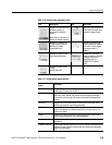
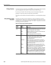
Table 2-12: Setup output parameter operations (cont.)
Bottom
button
Side
button Description