


Appendix B: Performance Verification (AWG710B)
B-20 AWG710&AWG710B Arbitrary Waveform Generator User Manual
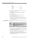
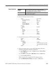
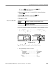
2. Set the DMM controls as follows:
3. Follow the substeps below to set the AWG710B Arbitrary Waveform
Generator controls and to select the sequence file:
a. Push UTILITY (front–panel)!System (bottom)!Factory Reset
(side)!OK (side).
b. Push SETUP (front–panel)!Run Mode (bottom)!Enhanced (side).
The AWG710B Arbitrary Waveform Generator is set to enhanced mode.
c. Load the AMP1.SEQ file.
Refer to Loading Files on page B-9 for file loading procedures.
4. Push the RUN and CH1 output buttons.
The LEDs above the RUN button and CH1 output connector are on.
5. Do the following substeps to set the AWG710B Arbitrary Waveform
Generator amplitude and confirm the offset setting:
a. Push VERTICAL MENU (front–panel)!Amplitude (side).
b. Push 0, ., 0, 2 and ENTER keys in this order or turn the general purpose
knob to set the amplitude to 0.020 V.
c. Verify that the offset setting display on the Offset side button is 0.000 V.
If the offset display is not set correctly, push the Offset side button, and push
0 and then ENTER key.
6. Do the following substeps to check the amplitude accuracy of a 20 mV
amplitude setting:
a. Write the DMM reading as a positive voltage.
b. Push the FORCE EVENT button.
c. Write the DMM reading as a negative voltage.
d. Verify that the positive minus negative voltages fall within
20 mV ± 2.4 mV.
e. Push 0, ., 2 and ENTER keys in this order or turn the general purpose knob
to set the amplitude to 0.200 V.
7. Do the following to check the amplitude accuracy of 200 mV amplitude
setting:
a. Push the FORCE EVENT button.
b. Write the DMM reading as a positive voltage.
Mode. . . . . . . . . . . . . . . . . . . . . . . . . . . . . . . . . . . VDC
Range . . . . . . . . . . . . . . . . . . . . . . . . . . . . . . . . . . Auto
Input . . . . . . . . . . . . . . . . . . . . . . . . . . . . . . . . . . . Front